Week - 4
1. Washing Machine :
Description : Here, a simulink model is created which depicts the operation of a washing machine, implementing the control logic on the basis of the conditions given in the question which are :
- If the power supply is available, the system gets activated
- If the Water supply is not available, stop the process & indicate through LED
- Soaking time should be 200s followed by Washing time of 100s.
- Then rinsing happens for next 20s & dryer runs for 50s
At first, the control logic to be implemented is created using the stateflow as shown in fig 1.1; depicting the operation of the washing machine.Here, power_supply and water_supply are selected as the inputs of the chart and water_level, cycle, dryer, rinse, soak and wash are taken as the outputs of the chart. When both power supply and water supply(both =1) is given, the washing machine starts operating and when water supply is not provided, it stops operating. During its operation, its soaks for a time of 200 sec, followed by a washing time of 100 sec. Then, it is rinsed for a time of 20 sec and sent to a dryer to dry the clothes for a time of 50 sec. The power and water supply constant blocks are taken as inputs and the outputs are the display blocks of cycle, dryer, rinse, soak, wash and water_level(as in fig 1.2).
fig 1.1 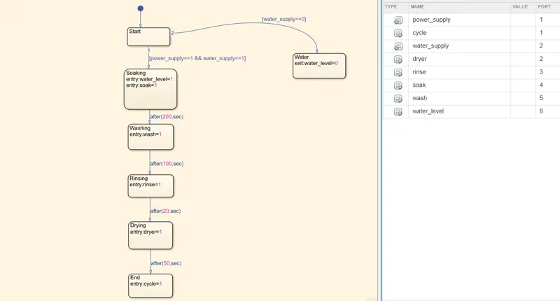 fig 1.2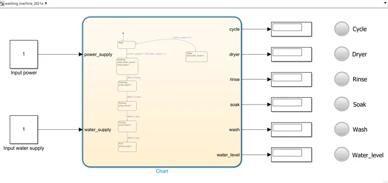
Result : Here when input= 1; means that an input value/supply is given to the chart and input= 0; means no input value/supply is given. Also as shown in fig 1.3; red light in the lamp indicates no particular processes had occured and as in fig 1.4, green light indicates that the particular processes have been completed.
- Condition 1 : Here, the power supply is given(value= 1), but the water supply is not given, ie the input water supply block value= 0. In this case, it does not execute soak,rinse and other processes and jumps out of the loop to another block indicating no water_level in the control logic(fig 1.3). Here, all the lamps are red in colour indicating that no processes are performed and completed with the output display blocks having the value= 0.
- Condition 2 : Here, both power supply and water supply is provided, ie both the input blocks will have a value= 1. In this case, it executes the loop and performs all the operations such as soaking for a time of 200 sec, washing for a time of 100 sec, rinsing for 20 sec, followed by drying for about 50 sec. Then, after the completion of all the above processes, a cycle is completed in the control logic and the next cycle may/may not be started depending upon the need of the user(fig 1.4). Here, all lamps are green in colour indicating all the processes are completed along with cycle being completed with the output display blocks having the value= 1.
fig 1.3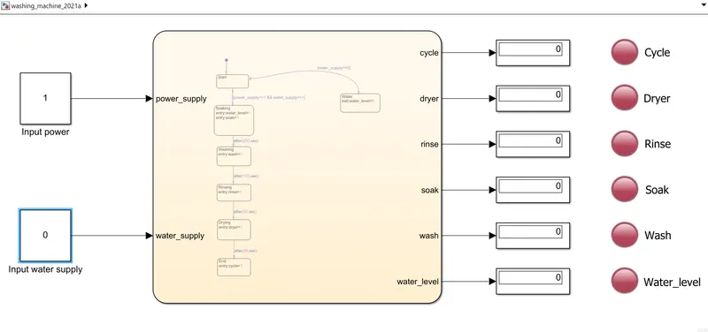 fig 1.4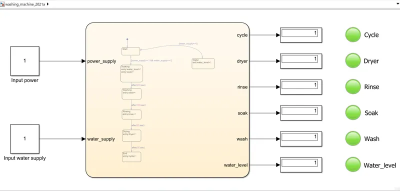
2. Gear shift :
Description : Here, a simulink chart is created depending on the conditions given below;
Speed Range(km/hr) Gear
0 to 15 1
16 to 25 2
26 to 40 3
41 to 60 4
Above 61 5
At first, the simulink chart of the gear shift is created using the stateflow to operate depending on the above conditions(as in fig 2.1). Here, speed is taken as the input of the chart and gear taken as the output of the chart. For the gear operation; at speed below 16 km/hr, gear 1 is operated and in the range of 16-25 km/hr, gear 2 is operated. Then for speeds in the range 26-40 km/hr, gear 3 is operated, in the range of 41-60 km/hr, gear 4 is operated and above 61 km/hr, gear 5 is used. Here, the input blocks used are a constant block of value 1 and a slider gain block.The slider gain block is used to vary the speed given in the input and determine the gear shifts in the output. The ouput is a display block showing the gear shifts(in fig 2.2). Hear the gear shift occurs in forward shift as well as reverse shift according to the control logic, where the suitable gear is selected for the corresponding speed range by the user.
fig 2.1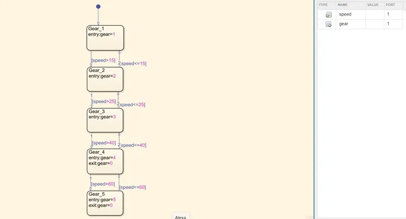 fig 2.2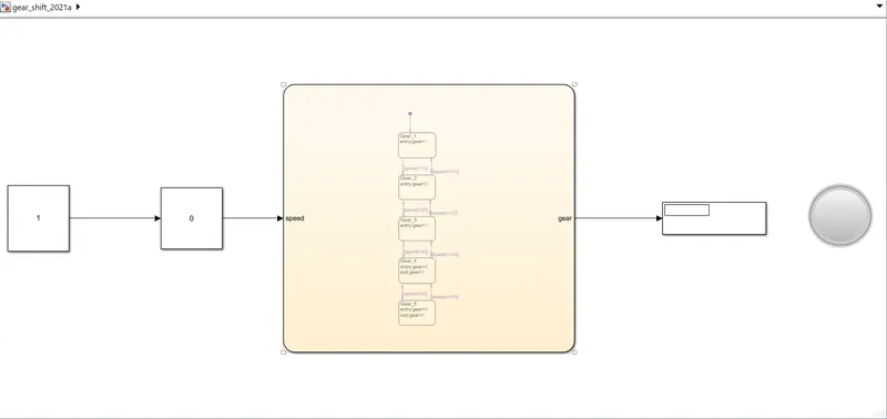
Result : It is explained on the basis of the gear shift. ie,
- Condition 1 : When the speed is in the range of 0-15 km/hr; ie, 9.1 km/hr, gear 1 is activated and the lamp shows green colour with the display block showing gear 1 as in fig 2.3;
fig 2.3 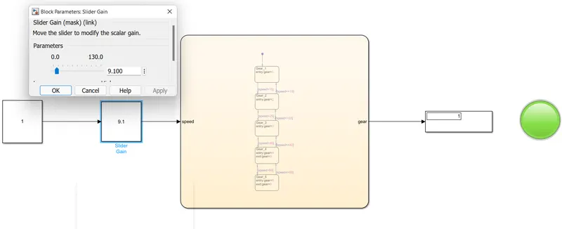
- Condition 2 : When the speed is in the range of 16-25 km/hr; ie, 19.5 km/hr, gear 2 is activated and the lamp shows blue colour with the display block showing gear 2 as in fig 2.4;
fig 2.4 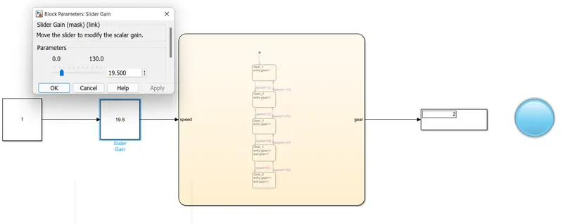
- Condition 3 : When the speed is in the range of 26-40 km/hr; ie, 35.10 km/hr, gear 3 is activated and the lamp shows yellow colour with the display block showing gear 3 as in fig 2.5;
fig 2.5 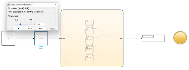
- Condition 4 : When the speed is in the range of 41-60 km/hr; ie, 50.7 km/hr, gear 4 is activated and the lamp shows violet colour with display block showing gear 4 as in fig 2.6;
fig 2.6 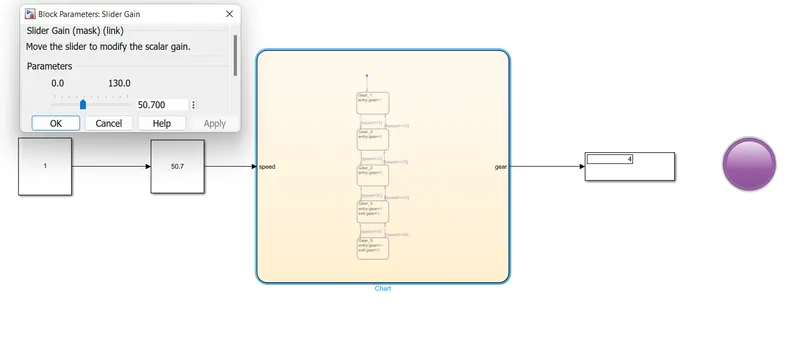
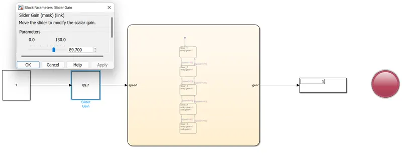
- Condition 5 : When the speed is above 61 km/hr; ie, 89.7 km/hr, gear 5 is activated and the lamp shows red colour with display block showing gear 5 as in fig 2.7;
fig 2.7