Week-6 Challenge: EV Drivetrain
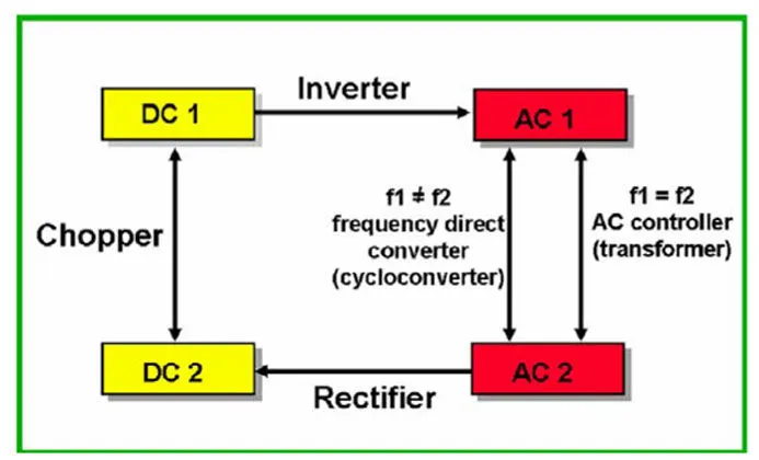
1. Types of Power converter circuits employed in electric and hybrid electric vehicle :
POWER CONVERTERS :
Power converters are semi-conductor devices that either converts power from AC to DC/constant DC to pulsating DC or changes the level of the power by changing the voltage/current parameter levels. A power converter is an electrical circuit that changes the electric energy from one form into another desired form which is optimized for a specific load.
Different power converters used in EVs :
- Battery charger : Consists of AC to DC converter, also termed as rectifiers.
- DC-DC converter/Chopper : For auxillary loads.
- Inverter : Converts DC voltage from battery to AC for the motor.
- AC-AC converter : AC voltage regulator.
- Bi-directional converter(for regeneration) : It allows the power flow in both the directions and contains AC-AC, DC-AC and DC-DC(choppers) converters in a single unit
Different power converters used in HEVs :
There is no specific difference between the converters used in EVs and HEVs if its purpose is taken into context. But in HEVs, instead of a bi-directional converter, a seperate regenerative DC-DC chopper is used to convert the mechanical energy from the gasoline engine to the alternatore for energy storage purposes.
Types of power converters used :
- AC-DC converters(Controlled rectifiers) : Here, these converter circuits can convert the AC voltage into the DC voltage. The DC output voltage can be controlled by varying the firing angle of the thyristors. The AC input voltage provided could be a single phase or three phase.
- DC-DC converters(DC choppers) : These converters converts a fixed DC input voltage into a variable DC voltage or vice-versa. The DC output voltage is controlled by varying the duty cycle.
- AC-AC converters(AC voltage regulator) : These converters can convert a fixed AC input voltage to a variable AC output voltage. The output voltage is controlled by varying the firing angles of the TRIAC.
- DC-AC converters(Inverters) : These converters converts a fixed DC input voltage into a variable AC output voltage. The output voltage is controlled by changing the amplitude of the DC supply link and by changing the duty cycle of the control circuit. The DC-AC converters are used in vehicles to charge their batteries and these circuits are mainly used for driving low-power AC motors and in solar power systems.
2. EV steady state speed of an EV powertrain if the duty cycle is 70% :
As per the figure given in the question above, the given parameters are; Battery pack voltage(Vb)= 72 V, Rated armature voltage(Va)= 72 V and Rated armature current(Ia)= 400 A
Here, d1 and d2 are the acceleration and the braking duty cycles respectively.
Ra= 0.5 Ω and kɸ= 0.7 V-sec and the Chopper switching frequency= 400 Hz
The vehicle speed-torque characteristics equation is given as, Tv = 24.7+0.00051ω^2 ----------------(1)
Solution :
Duty cycle= 70% = 70/100 = 0.7
Actual voltage= 0.7*72 = 50.4 V
The Torque-Speed equation of the DC motor is given as; T= V.(kɸ/Ra)-((kɸ)^2/Ra).ω
T= V.(kɸ/Ra)-((kɸ)^2/Ra).ω = 50.4*0.7 / 0.5 - ((0.7)^2/0.5).ω
T= 70.56 - 0.98ω ---------------(2)
Solving the eqns are (1) and (2);
Comparing both the torque of the vehicle and the torque of the motor, then
24.7+(0.0051)ω^2 = 70.56 - (0.98)ω
0.0051ω^2 + 0.98ω - 45.86 = 0 ---------------(3)
Here, the eqn (3) represents the quadriatic equation;
ω= 38.915 rad/sec and ω= -231.072 rad/sec
So, the EV steady state speed of an EV powertrain if the duty cycle is 70% = 38.915 rad/sec or 317.6 rpm.
3. Mathematical model of a DC Motor for the below equation using Simulink : ω= V/kɸ - (Ra/(kɸ)^2).T
The simulink model of the DC motor using the given equation, ω= V/kɸ - (Ra/(kɸ)^2).T is given in the fig 3.1;
fig 3.1 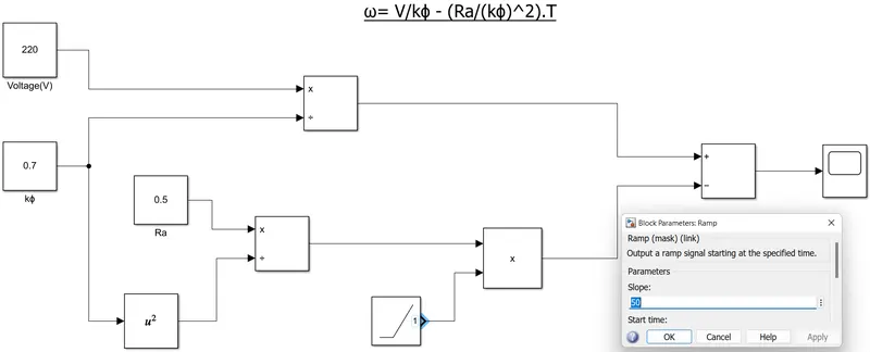
The above simulink model in the fig 3.1 depicts the model of a DC motor using the equation, ω= V/kɸ - (Ra/(kɸ)^2).T ; where a constant block is taken as the input voltage supply, V= 220 Volts and it is divided by a divide block with another constant block denoting kɸ= 0.7 and is connected to an add block. Then, another constant block denoting Ra= 0.5 is divided by a divide block with the square of the the constant kɸ block through a square block and is multiplied through a product block with a ramp input block denoting torque with a value of 50 and given to the add block. A scope is taken from the add block for getting the results of the equation above.
Results :
The Speed Vs Time plot of the mathematical model of a DC Motor for the below equation using Simulink : ω= V/kɸ - (Ra/(kɸ)^2).T is given below in fig 3.2, where it is observed that the speed(ω) decreases from 315 to -200 rpm during 0-10 sec; where it is seen that the speed(ω) is varying with respect to the torque applied.
fig 3.2 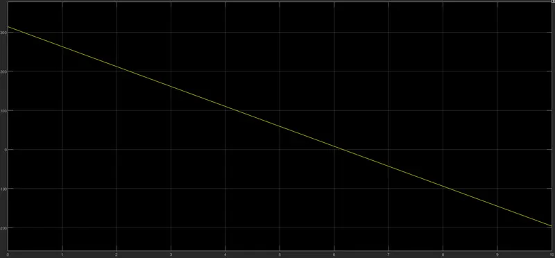
4. The author's perspective on the Induction Versus DC brushless motors :
INDUCTION MOTORS :
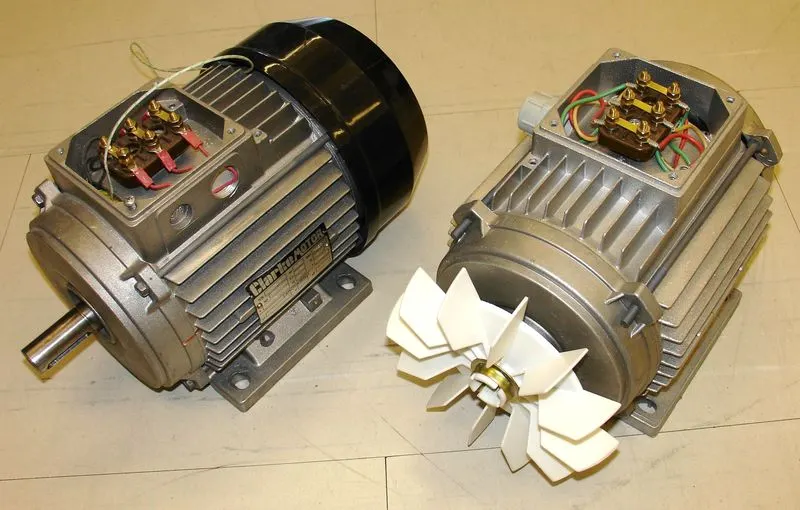
An induction motor or asynchronous motor is an AC electric motor in which the electric current in the rotor needed to produce torque is obtained by electromagnetic induction from the magnetic field of the stator winding. An induction motor can therefore be made without electrical connections to the rotor. An induction motor's rotor can be either wound type or squirrel-cage type rotor.
DC BRUSHLESS MOTORS :
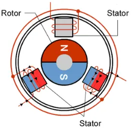
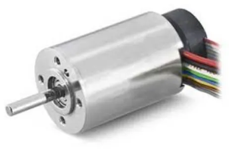
A brushless DC electric motor (BLDC motor or BL motor), also known as an electronically commutated motor (ECM or EC motor) or synchronous DC motor, is a synchronous motor using a direct current(DC) electric power supply. It uses an electronic controller to switch DC currents to the motor windings producing magnetic fields which effectively rotate in space and which the permanent magnet rotor follows. The controller adjusts the phase and amplitude of the DC current pulses to control the speed and torque of the motor.
According to author's perspective;
- There is no such thing called as the best engine. According to the personal requirements, we need to adapt the engine type.
- In the course of time, Lead-acid batteries are replaced by Lithium-ion batteries.
- In the course of time, DC brushed motors are replaced by the DC brushless or induction motors.
- In the course of time, the contactor controllers are replaced by modulating inverters.
- There is a bigger concern regarding the stable use of these elements mentioned above over the next few decades.
- The author discusses the two technologies: the DC brushless drives and the Induction motor with their respective operating features.
- The author says that the brushless motors are useless motors without the inverter.
- He also mentions that the 3-phase induction motors have great utility but with several limitations.
- The major limitation being that the induction motors cannot operate from DC and that an AC supply is a must.
- Further, he compares the future trends which may occur in DC brushless as well as induction motors
Conclusion : He concludes that the DC brushless drives will likely continue to dominate in the hybrid as well as the coming plug-in hybrid markets and that the induction drives will likely continue to maintain their dominance for high performance pure electric vehicles.