Week-7 Challenge: DC Motor Control
Week-7 Challenge: DC Motor Control
Aim:
To study and understand DC motor chopper drives using MATLAB and Simulink.
Objective:
- Answer the below questions
- Explain a MATLAB demo model named ‘Speed control of a DC motor using BJT H-bridge’.
- Comment on the armature current shoot-up from the scope results.
- Refer to the help section of ‘The Four-Quadrant Chopper DC Drive (DC7) block’. Compare it with the H-bridge model.
- Develop a 2-quadrant chopper using simulink & explain the working of the same with the relevant results. (Refer to article - Multiquadrant operation of motor)
- Explain in a brief about operation of BLDC motor.
Objective: 1
a.Explain a MATLAB demo model named ‘Speed control of a DC motor using BJT H-bridge’.
‘Speed control of a DC motor using BJT H-bridge’ is a simulink model to control DC motor using IGBTS to operate as BJTs.The difference between BJT and IGBT is that BJT uses current to control the switching of transistor where as IGBT uses voltage at the gate terminal, thus in this simulink model pulse signals (1/0) are being used for the switching of transistor which makes the IGBT to operate as BJT in this example.
Layout: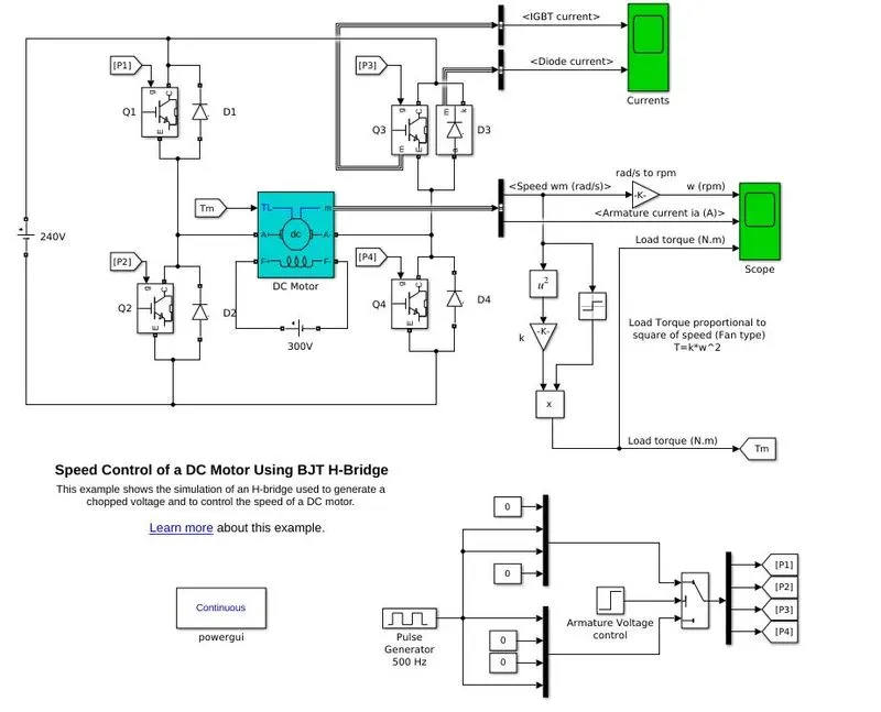
The DC supply voltage for the circuit is 240V. The layout consists of a brushed type DC motor of 5HP 240V 1750RPM with separately exited field winding of potential requirement of 300V DC supply. The motor gets controlled by 4 IGBTs (Simulated as BJTs) Q1 and Q4 for forward direction of rotation and Q2 and Q4 for reverse direction at desired speed range. Each of the transistors is paired with freewheeling diodes connected between the emitter and collector to loop the current inside the circuit when the transistor switch is closed during every cycle.
The DC motor block consists separate of input terminals for armature and field windings. It also consist of a load torque (TL) port as a mechanical input, where the load torque is proportional to the square of motor speed which is being calculated using math blocks from the signal output from the motor data bus, this load torque is being fed back to the motor TL port. The motor also consist of a measuring port m that sends out signal output through data bus which we discussed above.
The motor uses H-bridge circuit with 4 IGBTs (simulated as BJTs) with the pair of freewheeling diodes.
The motor terminal is connected in between diodes Q1 and Q4 for forward rotation and between Q2 and Q3 for reverse direction. When the gate signal is applied the transistor Q1 and Q4 switches are closed so the positive voltage is applied across the motor based on the duty cycle, when the transistor switch is open the current will be looped back in to the circuit through diodes D3 and D2 which keeps the motor to run in forward direction at controlled speed corresponding to the duty cycle.
When the gate signal is applied across transistor Q3 and Q2 the switches are closed so the negative signal is applied across the motor terminal to operate in reverse direction as per the duty cycle, when the switch is open the current will be looped back through diodes D4 and D1.
By which the DC motors are being controlled at desired speed with computed torque reference as input.
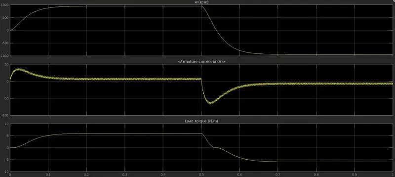
The input for the IGBTs is generated using pulse generator at 500Hz frequency and is converted to signal P1, P2, P3 and P4 for the transistors Q1, Q2, Q3 and Q4 respectively for the switching operation. The duty cycle of the pulse signal is 75% which supplies the input voltage as 180V (240V x 0.75%) to the motor. The total simulation time is 1sec where P1 and P4 signals are in ‘On’ state for 0.5 sec for the forward rotation of the motor. After 0.5 sec the signals P1 and P4 goes to ‘Off’ state where P2 and P3 turns ‘On’ which applied potential across the motor terminal in opposite direction causing to rotate in reverse direction.
The motor, transistor and diode have measurement ports by which the parameters required can be measured. The scope in the simulink model reads motor speed, torque, armature current; transistor current and diode current can be measured.
b.Comment on the armature current shoot-up from the scope results.
From the scope result we can observe that the armature current spikes up and brought down from the elevated range until the speed of the motor comes constant. This is because of the back EMF of the motor.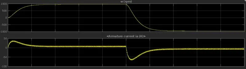
We know the motor equation is `V= E_b+ I_a R_a`
Where back emf `E_b` contributes a major role to the current drawn from the external circuit.
`E_b=(P∅NZ)/(60A)`
At the starting of the motor the armature resistance is very less as there is no back emf due to the non movement of the armature. Back emf generates in a motor due to the relative motion between the stator magnetic field and the armature conductor which induces the emf in the motor conductor that creates a generator effect. This opposing magnetic field causes resistance to the armature causing to increase the internal resistance across the rotor coils.
This resistance will be zero when the armature is held from rotation so maximum amount of current will be rushed through the armature circuit which causes the rotator to move, when the armature accelerates the back emf increases proportional to the speed of the motor as per the above back emf equation causes more resistance in the armature coil due to the opposing magnetic field in between the stator and the rotor, this effects causes resistance for the current to rush in to the armature circuit.
When the motor runs at the constant desired speed the armature current stabilizes with respect to the motor load and speed.
C.Refer to the help section of ‘The Four-Quadrant Chopper DC Drive (DC7) block’. Compare it with the H-bridge model.
|
Parameter |
Four -Quadrant Chopper DC Drive (DC7) |
H-bridge model |
|
Power source |
3 phase 380 V 5Hz AC supply |
Constant 240 V DC supply |
|
Motor |
Separately excited 200 HP DC motor |
Separately excited 5 HP DC motor |
|
Operation mode |
4 Quadrant |
4 Quadrant |
|
Regeneration energy |
Regenerative energy during braking is limited and can not be stored as there is no voltage storage available since the external source is a 3 phase AC. |
Regenerative energy during braking is not limited and can be stored to the DC power source which is a storage element also in this case is a battery. |
|
Construction |
DC7 block includes integrated drive system. It consists of a motor, converter and controller. The rectified DC supply is fed to the drive which consists of PI regulators for speed and current. The speed regulator outputs the current values to the current regulator based on input speed map where as the current regulator controls the switching of the IGBTs at 5KHz pulse rage with the computed duty cycles. |
Here the motor does not include the control regulators, the motor control is achieved thought external BJTs which is a current controlled IGBTs in this case. The transistor switching is done by means of the pulse signal at fixed duty cycle. The motor spinning direction is based on the pulse signal duty cycle proceed at 5KHz. |
|
Speed |
The speed of the DC motor is achieved through the speed reference map as input to the DC7 block speed input port. The speed reference is being varied though time with 400 rpm speed ramps per instance for acceleration and deceleration. |
Speed control of the DC motor is provided thought the pulse signal duty cycle, the desired speed of the DC motor remains contant. |
|
Torque |
The torque output of the motor is based on the external mechanical load provided in mechanical parameters as inertias and frictions. The torque feed back reference to the motor is computed by means of motor output speed with torque equations. |
The torque output of the motor is based on the external mechanical load provided in mechanical parameters as inertias and frictions. Same as like in DC7 block. The torque feed back reference to the motor is computed by means of motor output speed with torque equations. |
Objective: 2
Develop a 2-quadrant chopper using simulink & explain the working of the same with the relevant results. (Refer to article - Multiquadrant operation of motor )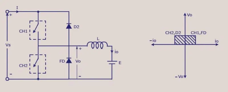
The 2 quadrant chopper is also known as Type-C or Class-C chopper operates at the 1st and 2nd quadrants as forward motoring and regenerative braking modes respectively.
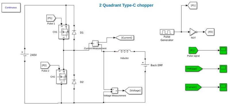
The circuit consists of an inductive load and a back emf source representing a DC or AC motor which is connected to the external voltage source through transistors CH1 and CH1 and diodes D1 and D2 respectively.
During forward motoring the transistor CH1 is closed and CH2 is held open so the voltage applied across the positive terminals of the motor load and the current flows in positive direction, i.e. from source to load, to overcome the effect transistor switching a freewheeling diode D2 is employed to circulate the current back to load, in this instance the transistor CH1 and diode D2 shorts the circuit causes motoring action.
During regenerative braking the motor acts as a generator and acts as a source while the battery is the load now, the voltage across the motor terminal is still positive but the current flows in the reverse direction, to facilitate that the transistor CH2 is closed and CH1 is held open, the current in negative direction flows to the battery through diode D2, to overcome the transistor switching effect the transistor CH2 closure forms a short circuit to circulate the voltage flow, together the diode and the transistor provides negative current across the motor terminal so the battery will get charged during regenerative braking.
Construction:
This 2 quadrant chopper model was created using simulink to demonstrate the working of chopper in 1st and 2nd quadrant as motoring and regenerative braking modes as explained earlier.
The construction of the model consists of a central load i.e. inductor as motor armature winding and a DC source (120 V) as back EMF together representing the motor. The external source is a 240 V DC supply from source such as battery. 2 MOSFETS CH1 and CH2 are connected with motor load as center and 2 freewheeling diodes D1 and D2 are connected in parallel with the MOSFETS CH1 and CH2 respectively. The voltage measurement block is connected across the motor terminal and is connected to a ‘Go to’ tag named ‘Voltage’.
The current measurement block is connected in series with the motor and the measurement is sent to a ‘Go to’ tag names ‘current’. The switching signal to the MOSFET is produced from a pulse generator as P1 and P2 for CH1 and CH2 respectively. The control signal, voltage measurement and current measurement can be viewed through their respective scopes connected to the ‘From’ tag as mentioned in green. (Note: Online Simulink does not facilitate 3 view ports on the same scope, so using individual scopes for each parameter measurements)
Working:
From the above circuit the motor requires a forward voltage and current to be applied across the terminal so the potential from the battery is fed in to the motor causing a forward turn thus makes a 1st quadrant operation of the DC motor. For which the MOSFET CH1 have set be closed and CH2 have to be held open for that time, for that purpose a pulse signal P1 is connected to the MOSFET CH1 and signal P2 is connected to MOSFET CH2 respectively. The signals P1 and P2 are generated using pulse generator of duty cycle 50% (can be varied) with amplitude 1 and time period 0.1 sec for easy understanding of sample. The original signal is connected to the P1 ‘Go to’ tag which in turn connected to CH1 to close MOSFET 1 during motoring operation, the pulse is also connected to a ‘Not gate’ block to produce signal P2 to close MOSFET 2 for regenerative braking operation, when the original signal produced is zero the ‘Not’ block converts it in to a signal for CH2 closing.
When CH1 is closed and CH2 is open the voltage (240 V) from the source is fed across the motor terminal as a voltage and the current direction is in positive direction so the motor starts to turn, the freewheeling diode D2 is used to loop back the emf generated by the motor in to the closed circuit. This reads the voltage and current as positive from the scope measurement.
When there is no signal due to the duty cycle the ‘Not gate’ converts that as a signal P2 and closed CH2 when CH1 is open, the back EMF connected to the motor is represented as the potential generated by the motor making it as a generator, the voltage across the motor terminal is positive direction since the motor didn’t changed its rotation direction, but the current now flows from motor to battery in opposite direction to charge the eternal source is called regenerative braking. The generated current flows through diode D2 to the battery and close the loop through MOSFET CH2, the CH2 also works for freewheeling action. This cycle repeat for 1 sec time set in the simulation as per the pulse frequency.
Observation:
Pulse signal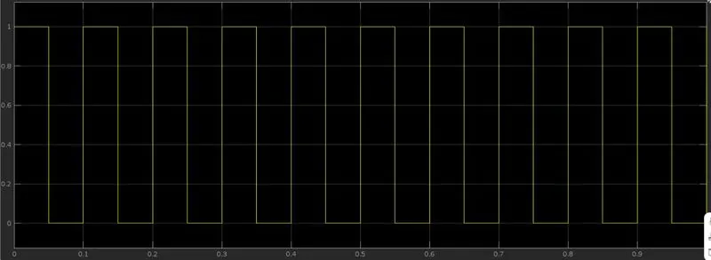
Voltage across terminal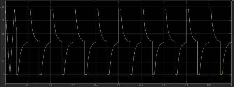
Current through system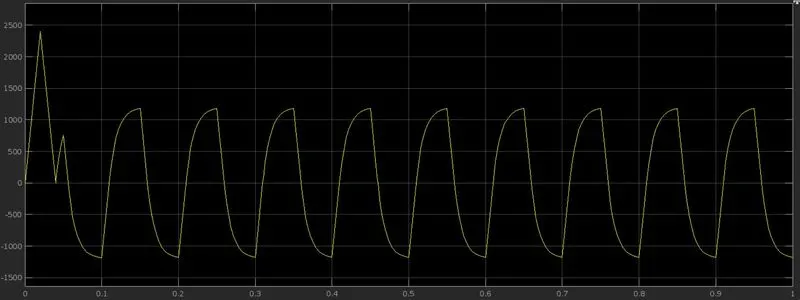
From the scope measurement we can observe the voltage tracing the path of the input pulse signal of duty cycle 50%, the latency caused due to the inductance and resistive effects of the inductor and MOSFETS.
The voltage measurement is always above 0 making it in a positive voltage and always remains in the positive of y-axis for one complete cycle i.e positive voltage in both motoring and braking mode, during motoring mode we can observe the actual supply voltage of 240V for the duty cycle 50%, when the pulse is low the back emf represented as generated voltage flowing back to the battery as 120 V.
From the current measurement scope we can observe that is fluctuating above and below zero, i.e. current is positive when the pulse is On in CH1 and off in CH2 causing the current to flow through the motor causing motoring action, when the pulse is Off in CH1 and On in CH2 the current flows from motor to battery which is shown in negative axis in the scope.
From the result we can conclude the chopper is working and making the system operable at 2 quadrant modes.
Model:
The simulink model for the experiment can be downloaded from the link provided below.
https://drive.google.com/file/d/1nQ8fcHrf4xxUAILJKdPIQr8rhcp5XM1S/view?usp=sharing
Objective: 3
Explain in a brief about operation of BLDC motor
BLDC (Brush Less DC motor) is a type of DC motor which works with general motor principle but does not have brush contact with the rotor to change the polarity of the field causing the motor to turn, rather than it uses computed signals and control the motor digitally making the operation smoother and efficient.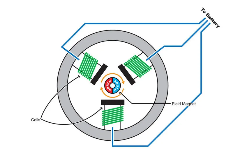
The Brush Less DC motor has a rotating permanent magnet and stationary electro magnets. It can be flipped inside out or can be constructed as conventional stator rotor arrangements.
The brushed motor have to turn 180° to flip the polarity of the rotating electromagnets to complete the 360° turn to accomplish 1 complete rotation, this mechanical set up employs carbon brushes and commutator rings that always makes frictional contact with one another. Where as in BLDC the stator and rotor are separated from each other without any physical contact for electricity commutation to keep continuous rotation of the motor, rather than the motor uses a control system that compute electronic signals to change the polarity of the electromagnets to keep the motor running while the rotor is always a permanent magnet with opposites polarities. The motor can be either shaft rotated or peripheral rotated type.
As stated above that the electronic controller circuit energizes appropriate motor winding by turning transistor to rotate the motor continuously.
Hall-effect sensors are used for position and speed feedback. The electronic controller can be a microcontroller or microprocessor. This controller receives these signals, processes them and sends the control signals to the transistor for motor drive.
In addition to the switching for a rated speed of the motor, additional electronic system changes the motor speed based on required application. These speed controls are generally implemented with PID controllers to have precise control. It is also possible to produce four-quadrant operation from the motor.
Advantages:
- It has no mechanical commutator and problems associated to that
- High efficiency due to the use of permanent magnet rotor
- High speed of operation
- Light weight and durable
- Good transient response
- Noise less operation
Disadvantages of Brushless Motor
- High development cost
- Electronic controller required control this motor is expensive
- Not much suitable for heavy load applications
- Requires monitoring systems for feed back
Applications:
- Electric and hybrid vehicles
- Computer drives
- Industrial robots and machine tools
- House hold Fans, pumps and blowers
Conclusion:
The DC motor and control devices were studied and understood. The given objectives were completed and output verified.