Week -2 Door bell mechanism and Heater control system simulation using Simulink
Aim:
- To simulate a door bell mechanism using solenoid block.
- To simulate a mechanism to sense temperature of a heater using thermistor and to turn on or off the fan.
Objective:
- To simulate a door bell mechanism using solenoid block.
- The electromagnet of the solenoid receives power from battery and pulls the metal arm to hit the bell producing sound.
- Create a situation where the switch is closed for 2 seconds and then released. Observe the physical movement of the plunger.
- To simulate a mechanism to sense temperature of a heater using thermistor and to turn on or off the fan at below condition.
- Temperature source: 20 °C from 0 to 10 seconds, 27 °C from 10 to 30 seconds, 23 °C from 30 to 50 seconds.
- Fan conditions: ON if the temperature above 25 °C, OFF otherwise.
Exercise:
Objective-1: To simulate a door bell mechanism using solenoid block.
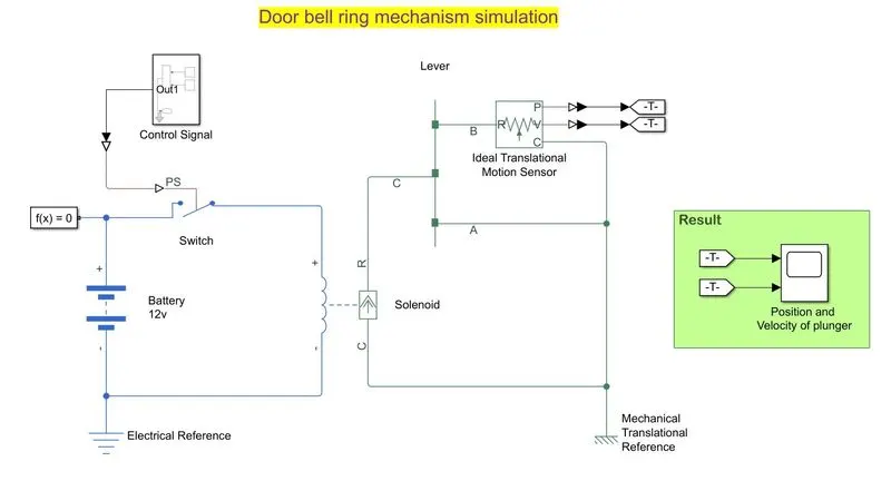
A simple model has been constructed to operate a door bell arm for 2 seconds when the switch is being pressed so as to allow electricity from the battery to flow through the solenoid causes the plunger to oscillate in a defined frequency, the plunger in turn causes the arm to vibrate to make it strike against the door bell.
Components used:
The components used in the simulation are as follows
- Battery (12V)
- Electrical reference
- Switch -Controlled by physical signal input
- Solenoid-5mm stroke at rated 12V DC supply
- Lever-0.2m span with one end pivoted and center hinged to solenoid
- Mechanical reference
- Ideal translation motion sensor
- Scope-To read the position and velocity of the bell arm.
- ‘Go-To’ and ‘From’ tags to send signal to scope
- PS-to simulink and Simulink-PS converters as required
- Sine wave, pulse generator and product math operator to generate control signal.
- Solver configuration.
Model construction:
- A blank model was created in simulink under the file name ‘Door_bell.slx’
- The simulation stop time of 12 secs has been assigned.
- A 12V Battery source is connected to the solenoid terminals with a ground reference
- A physical signal control switch is connected between the Batter and the Solenoid, The solenoid
- A solver configuration was added to the physical signal line
- A subsystem has been created in the name control signal to generate and the control signal so as the switch to operate based on. The control signal is made of sine waves and pulse generator with the use of product operator.
- The control signal sub system is connected to the switch using a Simulink-PS converter.
- The C port of the solenoid is connected to the mechanical translational reference.
- The R port of the solenoid I s connected to the C port of the lever.
- The A port of the lever is connected to the mechanical reference.
- The B port of the lever is connected to the Ideal translational sensor R port
- The C port of the I deal translational sensor is connected to the mechanical reference where as the P and V port are connected to 2 ‘Go-To’ tags which sends the position and velocity data to the 2 respective ‘From’ tags.
- A scope is connected to the 2 from tags to receive the position and velocity information of the lever arm to display in the result area.
Model explanation:
- The electrical source for the Door bell mechanism system is the a 12V battery connected to the Solenoid through a physical signal controlled switch.
- The switch closes when the signal is high and opens when the signal is low, the control signal to the switch was generated using the product of a sine wave of amplitude 1 and frequency 62.831853 rad/sec (i.e.10Hz, the arm will strike the bell 10 times a second) and pulse generator of amplitude 1 for the time period of 4 secs with the duty cycle of 50% which means the pulse signal will be high for 2 secs.
For the total simulation period of 12 seconds the Door bell will ring for 3 times for each time it will ring for the duration of 2 secs and a delay time of 2 secs. - The control signal is sent to the switch using a Simulink-PS converter.
- The signal will operate the solenoid causing it to vibrate at the frequency of 10Hz i.e, 10 oscillations of the plunger per second. The solenoid has been configured in a way that it will oscillated for the stroke of 5mm at the rated supply of 12V from the battery.
- A lever has been connected to the solenoid plunger, the lever is actually the arm that strike against the bell to produce sound. The number of oscillation of the plunger is the number of strikes the lever arm produce over the bell.
one end of the lever is connected to the mechanical reference where as the other end strikes against the bell, the pivot in the middle is connected to the plunger to put the arm in to vibration. - To measure the position and velocity of the arm that strikes against the bell an Ideal translational motion sensor has been connected to the lever which measures the position and velocity and send the signal to the scope with the help of 2 ‘Go-To’ and ‘From’ tags connected to the ‘P’ and ‘V’ ports of the sensor.
- A scope connected to the ‘From’ tags will receive the information of the position and velocity of the arm and plot it against time.
Output: Position and Velocity of the door bell lever
Plot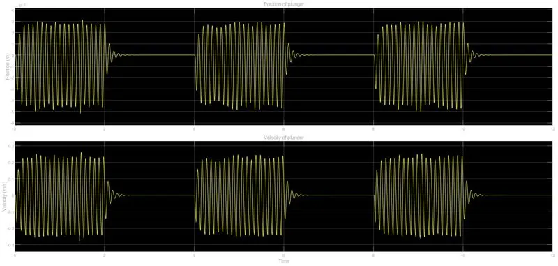
Simulink model:
The simulink model for the above project is provided in the below Google drive link in the file name ‘Door_bell.slx’
https://drive.google.com/file/d/1NWfWYE4eNBwd_E_LNtc3aNnKuXfbJtga/view?usp=sharing
Objective-2: To simulate a mechanism to sense temperature of a heater using Thermistor and to turn on or off the fan for specified temperature range.
A simulink model has been constructed to sense the temperature of a heater and to turn the cooling fan On when the temperature reaches above 25°C otherwise the fan will be Off with the help of a temperature sensing device known as Thermistor.
Thermistor- A thermistor is a thermally sensitive resistor that exhibits a change in resistance proportional to small changes in temperature.
There are 2 types of thermistors
- NTCthermistors, resistance decreases as temperature rises.
- PTCthermistors, resistance increases as temperature rises.
These thermistors when connected to a voltage source gives a potential difference which when connected to the wheatstone bridge the variation in voltage with the resistance due to heat can be recorded. This voltage signal can be used to operate other electrical devices mainly to control the system.
Components used:
The components used in the simulation are as follows
- Controlled temperature source
- Signal builder
- Thermal reference
- Temperature sensor
- Thermistor
- DC source (12V)
- Electrical reference
- Resistor (as required)
- Switch
- Controlled PWM voltage
- DC motor
- Mechanical rotational reference
- Ideal mechanical rotational inertia
- Ideal rotational motion sensor
- Voltage sensor (as required)
- Current sensor
- Simulink-PS and PS-Simulink convertors (as required)
- ‘Go-To’ and ‘From’ tags (as required)
- Scope (as required)
- Solver configuration
Model construction:
- A blank model was created in simulink under the file name ‘Thermistor.slx’
- The simulation stop time of 50 secs has been assigned.
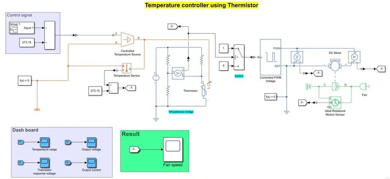
- A controlled temperature source considered as a heater has been included the blank model and port A of the temperature source has been connected to the thermal reference and port S is connected to the physical signal input.
- A Simulink-PS converter is used in between the controlled temperature source and the signal builder. The signal builder is the one which generates temperature signal for the given condition.
- A temperature sensor is connected across the port A and port B of the controlled temperature source and the sensor output is connected to a scope using PS-Simulink converter.
- The output port B of the temperature source is connected to the input port A of the Thermistor .
- The positive and negative terminal of the Thermistor is connected to a wheatstone bridge consist of 3 equal resistors used to find the potential difference across the junction, this circuit is being powered by a DC source of 12V with an electrical reference.
- The potential difference at the junction acts as the input signal for the fan to turn it On or Off. A voltage sensor is also connected at the junction to measure the cooling fan control voltage.
- A switch is connected to the wheatstone bridge voltage terminal to close and open when the input is high and low respectively using a PS-Simulink converter.
- The switch is then connected to the Controlled PWM voltage block of PS-input choice.
- The PWM port of the Controlled PWM source is connected to the positive terminal of a DC motor and the REF port is connected to the negative terminal of the DC motor with a common ground reference.
- A voltage sensor is connected across the PWM terminals and a current sensor is connected in series with the DC motor.
- The reference port C of the DC motor is connected to a mechanical rotational reference and the R port is connected to ideal mechanical rotational inertia which is considered as the cooling fan.
- An ideal rotational motion sensor is connected to the DC motor to sense the rotation by connecting the C port to the rotational reference and the R port to the spindle of the motor. The W port of the sensor meant for velocity reading is connected to the scope to monitor the fan speed.
- The output from each sensor is connected to ‘Go-To’ tags which sends signal to the ‘From’ tags so the output will be displayed in the scope which is connected to the ‘From’ tag.
- The sources parameter can be monitored using the scopes available in the ‘Dashboard’ panel.
- The function of cooling fan can be monitored using the scope available in the ‘Result’ panel.
Model explanation:
- The controlled temperature source connected to the Thermistor here is the component producsing heat at the defined range to the system, This temperature source produce heat based on the input temperature control signal for the specified range of temperature.The temperature signal is generated using signal builder for the condition like below,
Temperature source: 20 °C from 0 to 10 seconds, 27 °C from 10 to 30 seconds, 23 °C from 30 to 50 seconds.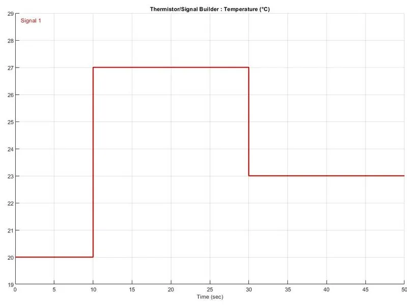
- A temperature sensor has been connected across the controlled temperature source to monitor the heater temperature for the time period of 50secs.
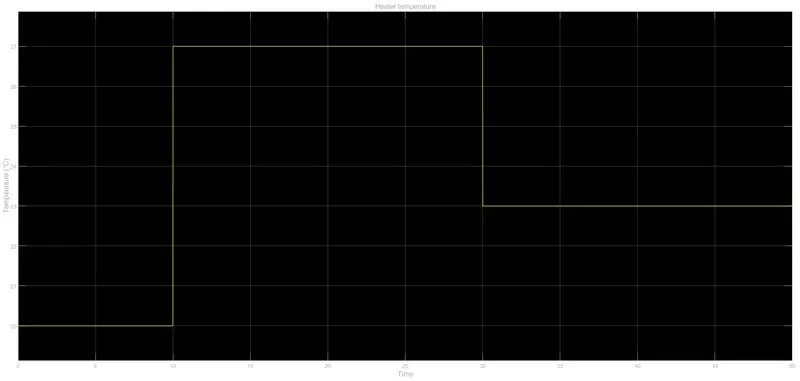
- The output of the temperature source is connected to the thermistor A port. The positive and negative terminal of the thermistor is connected to the wheatstone bridge.
- Wheatstone bridge- Wheatstone bridge, also known as the resistance bridge, is used to calculate the unknown resistance by balancing two legs of the bridge circuit, of which one leg includes the component of unknown resistance. The circuit is composed of three known resistors (in ideal condition), one unknown resistor.
The Wheatstone bridge works on the principle of null deflection, i.e. the ratio of their resistances are equal and no current flows through the circuit. When the bridge is in the unbalanced condition where current flows through the galvanometer.
when one of the resistor different from the other 3 the circuit becomes unbalanced and current flows through the voltmeter which can be used as the control signal for the cooling fan.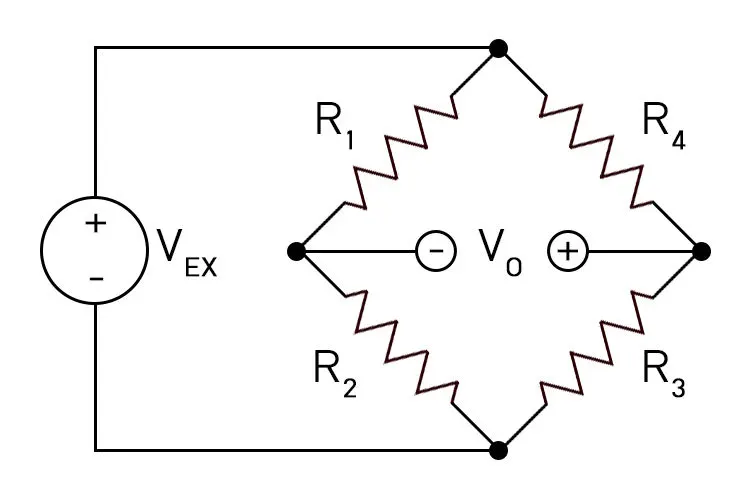
- The voltage from the wheatestone bridge junction is used to control the DC motor which drives the cooling fan.
The thermistor voltage response monitored is as below,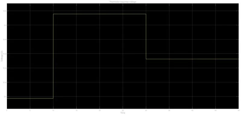
From calculation the response voltage for 25°C from the wheatstone bridge is 5.585V which can be used as the threshold value for the switch to signal high for the PWM source. The switch used has 2 constants 0 and 1 for the output Low and High to be sent to the PWM voltage block. - When the response voltage is above 5.585V the switch sends the signal High to the PWM block and the PWM control voltage of 12V at 100% duty cycle will be supplied to the DC motor to turn On. When the response temperature from the wheatstone bridge drops below the threshold value 5.585 for the switch the PWM will be commanded Low for no voltage to flow to the DC motor.
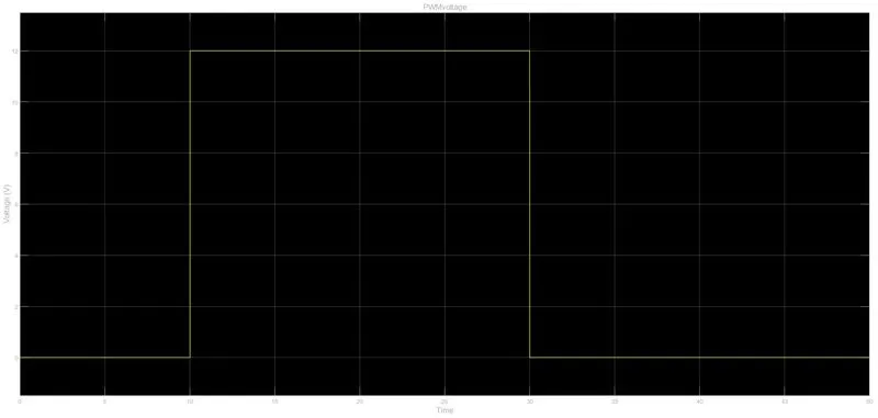
- The DC motor configured for 6V is connected to the rotational inertia considered as the cooling fan, the mechanical rotational sensor connected to the spindle of the fan measures the speed of the fan in rpm and plot it against the time span 50secs to record the function of the cooling fan.
- The output from each sensor is connected to the ‘Go-To’ tags which sends signal to the ‘From’ tag when in connection with the scope the different parameters can be monitored from the ‘Dashboard’ panel.
- The output of the fan, i.e. the On-Off condition of the cooling fan can be monitored from the scope in the ‘Result’ panel.
Output: Cooling fan behavior
The cooling fan is ‘On’ when the temperature reaches above 25°C during the time period between 10 to 30secs.
After 30 secs the cooling fan turns ‘Off’.
Plot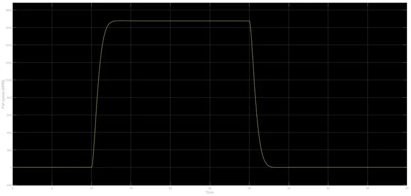
Simulink model:
The simulink model for the above project is provided in the below Google drive link in the file name ‘Thermistor.slx’
https://drive.google.com/file/d/1v8CX--Q5D5QeVm_ZfFFCuycL_b6qDh-g/view?usp=sharing
Conclusion:
Thus the Door bell mechanism and the Temperature control system using thermistor has been simulated using simscape and the model has been uploaded to the Google drive link provided in the report.