Week-7 Challenge: DC Motor Control
EV LIVE BATCH 21
QUES. 1 A
This example shows the simulation of an H-Bridge used to generate a chopped voltage & to control the speed of a DC motor
here, a simple H-bridge is controlling the speed od the motor.
H-BRIDGE:
It is the method of controlling the motor operation using the switching action of the switch at a certain switching frequency. In this model, IGBTs are used as a switch.
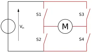
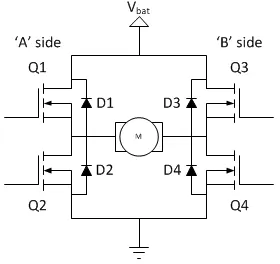
The switching elements(Q1,..,Q4) are usually bi-polar or FET transistors, in some high-voltage application IGBTs. The diodes(D1,..,D4) are called catch diodes and are usually of Schottky type.
The basic mode of operation of a H-Bridge:
- Q1 & Q4 are turned ON or Q2 & Q3 are turned ON
- The direction of rotation will depend upon the mode of operation
The BJT when used for power switching applications, operates as an IGBT. When it is conducting, a forward voltage Vf is developed between collector and emitte(in the range 1V).Therefore, the IGBT block can be used to model the BJT device.
The IGBT block does not simulate the gate current controlling the BJT or IGBT. The switch is controlled by a simulink signal(1/10). The DC motos uses the present model(5 HP 24V 1750 rpm). It simulates a fan type load(where lad torque is proportional to the square of speed). The armature means voltage can be varied from 0 to 240V when the duty cycle(specified in the Pulse Generator Block) is varied from 0 to 100%.
The H-bridge consists of four BJT/Diode pairs (BJT simulated by IGBT models). Two transistors are switched simultaneously: Q1 and Q4 or Q2 and Q3. When Q1 and Q4 are fired, a positive voltage is applied to the motor, and diodes D2-D3 operate as free wheeling diodes when Q1 and Q4 are switched off. When Q2 and Q3 are fired, a negative voltage is applied to the motor, and diodes D1-D4 operate as free-wheeling diodes when Q2 and Q3 are switched off.
QUES. 1 B
The motor starts in the positive directin with a duty cycle of 75%(mean DC voltage of 180). At t=0.5sec, the armature voltage is suddendly reversed and the motor runs in the negative direction.
Due to sudden changes in polarity of armature voltag, the overshoot current appears in the graph because the motor windings are inductor type so due to armature inductance which tries to oppose the sudden change in current direction and tries to maintain the stable current level.
QUES. 1 C
| FOUR-QUAD CHOPPER DC MOTOR | H-BRIDGE |
|
|
|
|
|
|
|
|
|
|
QUES. 2
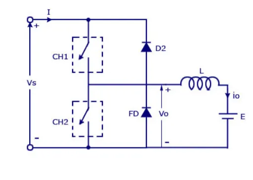
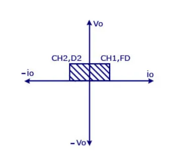
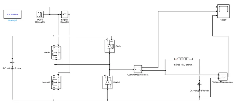
Circuit Diagram of two-quadrant chopper
SIMULINK MODEL:
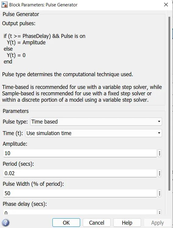
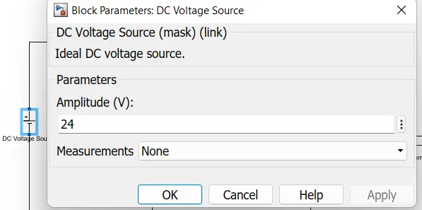
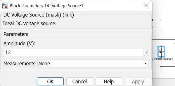
INPUT BLOCK PARAMETERS

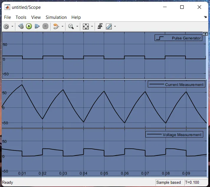
OUTPUT
QUES. 3
WORKING OF BLDC MOTOR
The underlying principles for the working of a BLDC motor are the same as for a brushed DC motor; i.e., internal shaft position feedback.
In case of a brushed DC motor, feedback is implemented using a mechanical commutator and brushes.
Whereas, in BLDC motor, it is achieved using multiple feedback sensors.
The most commonly used sensors are hall sensors and optical encoders. Hall sensors work on the hall-effect principle that when a current-carrying conductor is exposed to the magnetic field, charge carriers experience a force based on the voltage developed across the two sides of the conductor. If the direction of the magnetic field is reversed, the voltage developed will reverse as well.
For Hall-effect sensors used in BLDC motors, whenever rotor magnetic poles (N or S) pass near the hall sensor, they generate a HIGH or LOW level signal, which can be used to determine the position of the shaft.
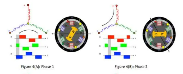
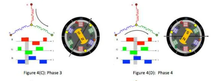
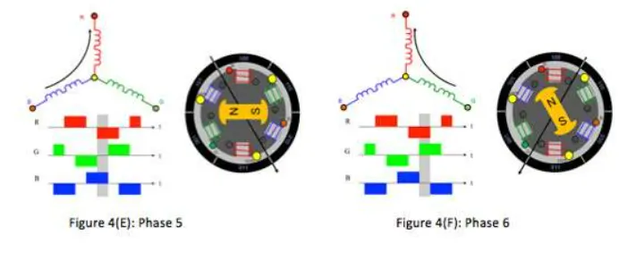
In a commutation system - one that is based on the position of the motor identified using feedback sensors - two of the three electrical windings are energized at a time as shown below.
In figure 4 (A), the GREEN winding labeled "001" is energized as the NORTH pole and the BLUE winding labeled as "010" is energized as the SOUTH pole. Because of this excitation, the SOUTH pole of the rotor aligns with the GREEN winding and the NORTH pole aligns with the RED winding labeled "100". In order to move the rotor, the "RED" and "BLUE" windings are energized in the direction shown in figure 4(B). This causes the RED winding to become the NORTH pole and the BLUE winding to become the SOUTH pole. This shifting of the magnetic field in the stator produces torque because of the development of repulsion (Red winding - NORTH-NORTH alignment) and attraction forces (BLUE winding - NORTH-SOUTH alignment), which moves the rotor in the clockwise direction.
This torque is at its maximum when the rotor starts to move, but it reduces as the two fields allign to each other.
Thus, to preserve the torque or to build up the rotation, the magneic field generated by stator should keep switching.
To catch up with the field generated by the stator, the rotor will keep rotating. Since, the magnetic field of both the stator and rotor rotates at the same frequency, they come under the category of synchronous motor.
REFERENCE: Detailed Brushless DC Motor Working Principle and Applications (robu.in)
Brushless DC Motors – Part I: Construction and Operating Principles - EDN