Week-7 Challenge: DC Motor Control
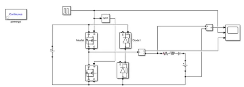
Q1. Explain a MATLAB demo model named ‘Speed control of a DC motor using BJT H-bridge’
BJT- H Bridge:
The bipolar junction transistor (BJT) when used for power switching applications, operates as an IGBT. When it is conducting (BJT operating in the saturated region), a forward voltage Vf is developed between collector and emitter (in the range of 1 V). therefore, the IGBT block can be used to model the BJT device. The IGBT block does not simulate the gate current controlling the BJT or IGBT. The switch is controlled by a Simulink signal. The DC motor uses the pre-set model (5 HP 24V 1750 rpm). It simulates a fan type load (where load torque is proportional to square of speed). The armatures mean voltage can be varied from 0 to 240 V when the duty cycle (specified in the Pulse Generator Block) is varied from 0 to 100%.
The H – Bridge consists of four BJT/Diode pairs (BJT simulated by IGBT models). Two transistors are switched simultaneously: Q1 and Q4 or Q2 and Q3. When Q1 and Q2 are fired, a positive voltage is applied to the motor and diodes D1-D3 operate as free-wheeling diodes when Q and Q4 are switched off. When Q2 and Q3 are fired, a negative voltage is applied to the motor and diodes D1-D4 operate as free-wheeling diodes when Q2 and Q3 are switched off.
Chopper:
A chopper circuit is any of numerous types of electronic switching devices and circuits used in power control and signal applications. A chopper is a device that converts fixed DC input to a variable DC output voltage directly. Essentially, a chopper is an electronic switch that is used to interrupt one signal under the control of another.
In power electronics applications, since the switching element is either fully on or fully off, its losses are low and the circuit can provide high efficiency. However, the current supplied to the load is discontinuous and may require smoothing or a high switching frequency to avoid undesirable effects. In signal processing circuits, use of a chopper stabilizes a system against drift of electronic components; the original signal can be recovered after amplification or other processing by a synchronous demodulator that essentially un-does the "chopping" process. Choppers are two types step down chopper and step-up chopper.
Process:
- Run the MATLAB demo ‘speed control of a DC motor using BJT-H Bridge’. The armature current shoot-up from the scope results is to observed.
- Open the MATLAB and in the help documentation type speed control of a DC motor using BJT- H Bridge.
Results tab opens, and then select the model and click Open model.
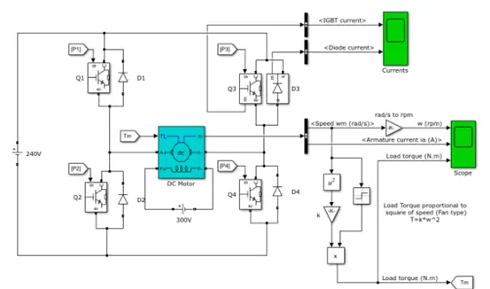
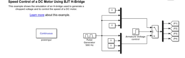
- The model is opened in Simulink workspace.
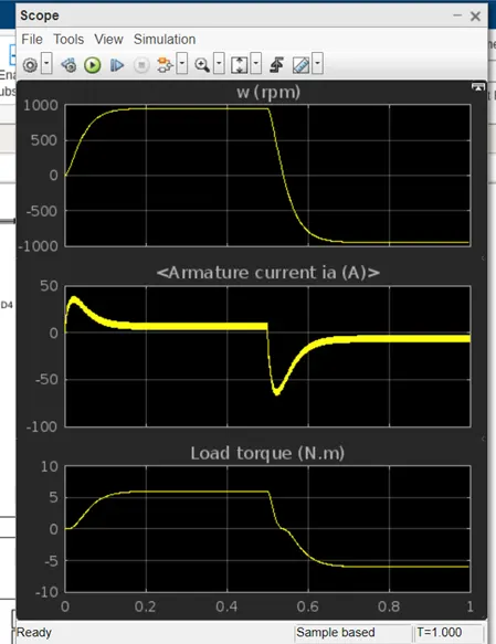
- Run the model as it is and observe the graphs of the armature current.
- Now, at the bottom part of the model, there’s a pulse generator block, click on it and run the model.
- Check the outputs. Follow the same for 75% and 50% just check if the armature voltage is decreased sharply after half of the simulation time.
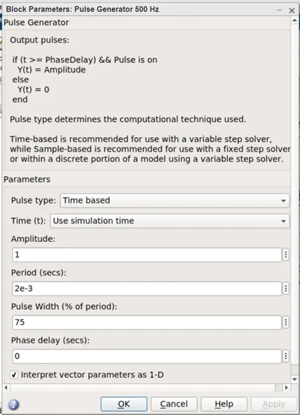
- Now change the pulse width to 50%.
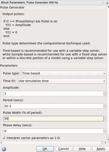
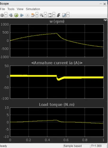
- As pulse width decreases the step up value of the armature current decreases.
Four quadrant chopper DC drive block:
The Four-Quadrant Chopper DC Drive (DC7) block represents a four-quadrant, DC-supplied, chopper (or DC-DC PWM converter) drive for DC motors. This drive features closed-loop speed control with four-quadrant operation. The speed control loop outputs the reference armature current of the machine. Using a PI current controller, the chopper duty cycle corresponding to the commanded armature current is derived. This duty cycle is then compared with a sawtooth carrier signal to obtain the required PWM signals for the chopper.
The main advantage of this drive, compared with other DC drives, is that it can operate in all four quadrants (forward motoring, reverse regeneration, reverse motoring, and forward regeneration). In addition, due to the use of high switching frequency DC-DC converters, a lower armature current ripple (compared with thyristor-based DC drives) is obtained. However, four switching devices are required, which increases the complexity of the drive system.
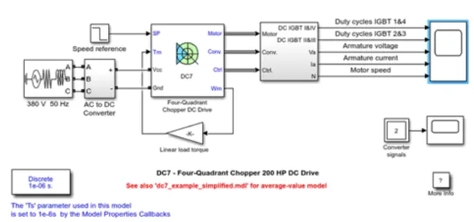
The 200 HP DC motor is seperately excited with a constant 150 V DC field voltage source. The armature voltage is provided by an IGBT converter controlled by two PI regulators. The converter is fed by a 515 V DC bus obtained by rectification of a 380 V AC 50 Hz voltage source. In order to limit the DC bus voltage during dynamic braking mode, a braking chopper has been added between the diode and the rectifier.
- The stability of the voltage and current supply is higher in the four qudrant compared to BJT as the four quadrant uses the step by step ramping stratedgy for the change in the motor direction whereas the stability is lost.
- Regerative braking is possible in four quadrant but not in BJT.
- It is widely used in automobile sector to control DC motor speed and direction in four quadrant. Whereas the BJT is used in robotics and electo-mechanical devices to control DC motor speed and direction.
- The current values are continuous in BJT and in four quadrant; it is chopped so that the simulation takes less time.
- To change the direction of the motor, current signals are interruped in four quadrants. Whereas in BJT the polarity of the current needs to be changed.
- The main advantage of four quadrant is that it operates in all the four quadrants but BJT can move only in two directions.
- Four quadrants provides better when compared to BJT that operates at moderate power levels.
Q2. Develop a 2-quadrant chopper using simulink & explain the working of the same with the relevant results.
The Two-Quadrant Chopper DC Drive (DC6) block represents a two-quadrant, DC-supplied, chopper (or DC-DC PWM converter) drive for DC motors. This drive features closed-loop speed control with two-quadrant operation. The speed control loop outputs the reference armature current of the machine. Using a PI current controller, the chopper duty cycle corresponding to the commanded armature current is derived. This duty cycle is then compared with a sawtooth carrier signal to obtain the required PWM signals for the chopper.
The main advantages of this drive, compared with other DC drives, are its implementation simplicity and that it can operate in two quadrants (forward motoring and reverse regeneration). In addition, due to the use of high switching frequency DC-DC converters, a lower armature current ripple (compared with thyristor-based DC drives) is obtained. However, for all two-quadrant DC drives, reversible and regenerative operations (reverse motoring and forward regeneration), which are required in most DC drives, cannot be obtained.
The Two-Quadrant Chopper DC Drive block uses these blocks from the Electric Drives/Fundamental Drive Blocks library:
- Speed Controller (DC)
- Regulation Switch
- Chopper
Q3. Explain in a brief about operation of BLDC motor.
A motor converts electrical energy into mechanical energy supplied. The brushless DC motors (BLDC) They provide high efficiency and excellent controllability and are widely used in many applications. The simplest type of engine is the DC brushed motor. In this type of engine, the electric current passing through coils arranged within a fixed magnetic field. The current generates magnetic fields in the coils; this rotates the coil assembly, since each coil is pushed away from the similar pole and pulled towards the unlike pole of the fixed field. To keep the rotation, you must constantly turn the tide, so that the polarity of the coil is constantly tipping over, causing the coils continue to “run after” the opposite poles. The power supply to the coils is provided through brushes Fixed conductive who come into contact with a switch rotating; It is the rotation of the switch which causes the reversal of the current through the coils. The commutator and brushes are the key components that distinguish the brushed DC motor by other engine types.
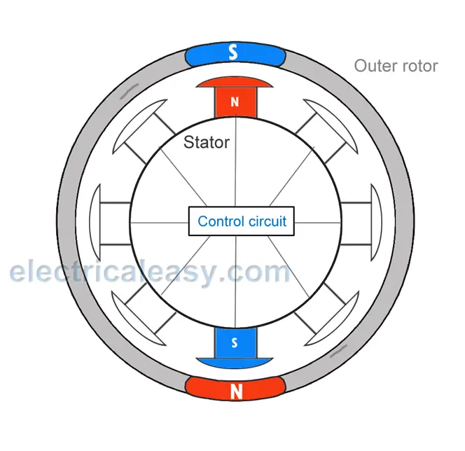
It illustrates the general principle of the brushed motor. The DC brushed motors, characterized by a simple design and simple control, they are widely used for opening and closing the tray of CD / DVD / BLU-RAY. In cars, they are often used to retract, extend and position the side mirrors to power supply. The low cost of these engines makes them suitable for many uses. one drawback, however, It is that the brushes and the switches tend to wear out relatively quickly as a result of their continuous contact, requiring frequent replacement and periodic maintenance. The stepper motor is driven by pulses; rotates through a specific angle (step) with each pulse. Since the rotation is controlled accurately by the number of pulses received, these motors are widely used to implement positional adjustments. They are often used, for controlling the supply of paper in printers, since these devices feed the paper in fixed steps, which are easily related to the pulse count. A pause can also be easily controlled, since the rotation of the motor is interrupted instantly when the pulse signal is interrupted.
With synchronous motors, the rotation is synchronous with the frequency of the supply current. These motors are often used to drive the rotating trays in microwave ovens; reduction gears in the motor unit can be used to obtain the appropriate speed of rotation. Even with induction motors, the rotation speed varies with the frequency; but the movement is not synchronous. In the past, these engines were often used in electric fans and in washing machines.
Advantages of BLDC motor:
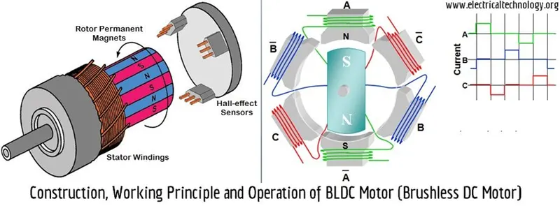
A BLDC motor with three coils on the stator will have six electrical wires (two for each coil) which extend from these coils. In most of the three implementations of these wires will be connected internally, with the three remaining wires that extend from the body of the motor (in contrast with the two wires that extend from the engine previously described brushes). The wiring in the houses of the BLDC motor is more complicated than the simple connection of the positive and negative terminals to power; I will examine more closely how these later engines. Now I take care of advantages of BLDC motors.
A big advantage is the efficiency, in these engines they must be continually at the maximum rotational force (couple). I brushed motors, Unlike, reach the maximum torque only at certain points of the rotation. For a brushed motor produces the same torque of a brushless model, you need to use larger magnets. This is the reason why even small BLDC motors can provide a remarkable power.
The second big advantage, linked to the first, and the controllability. The BLDC motors can be controlled, using feedback mechanisms, to accurately deliver the torque and the rotational speed desired. The precision control in turn reduces the power consumption and heat generation and, in cases where the motors are battery powered, lengthens battery life.
The BLDC motors also offer high durability and a low electrical noise generation, thanks to the lack of brushes. With brushed motors, the brushes and commutator wear out due to the continuous contact in motion and also produce sparks in case of contact. The electrical noise, in particular, It is the result of strong sparks that tend to occur in areas where the brushes pass over the blanks of the switch. This is why the BLDC motors are often considered preferable in applications where it is important to avoid electrical noise.