Week-7 Challenge: DC Motor Control
ANSWER 1A:
SPEED CONTROL OF DC MOTOR USING BJT H BRIDGE:
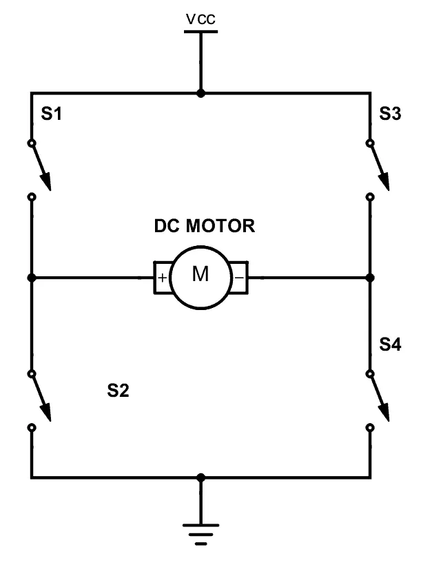
A DC motor spins either backward or forward, depending on how you connect the plus and the minus.
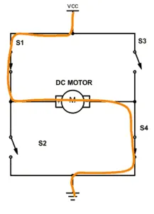
If you close switch 1 and 4, you have plus connected to the left side of the motor and minus to the other side. And the motor will start spinning in one direction.
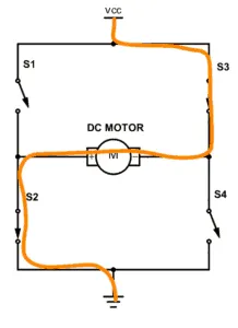
If you instead close switch 2 and 3, you have plus connected to the right side and minus to the left side. And the motor spins in the opposite direction.
If you add diodes in the reverse direction for the transistors, you give a path for the current to take to release this energy.
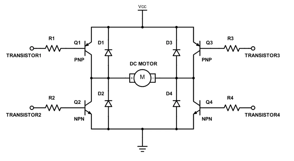
The model of speed control of dc motor using bjt h bridge is
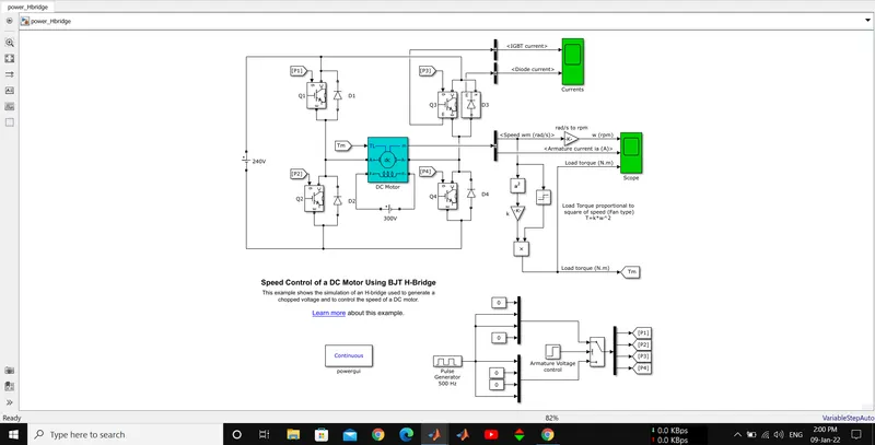
The H-bridge consists of four BJT/Diode pairs (BJT simulated by IGBT models). Two transistors are switched simultaneously:
Q1 and Q4 or Q2 and Q3.
When Q1 and Q4 are fired, a positive voltage is applied to the motor and diodes D2-D3 operate as free-wheeling diodes when Q1 and Q4 are switched off. and motor operates in forward motoring region.
When Q2 and Q3 are fired, a negative voltage is applied to the motor and diodes D1-D4 operate as free-wheeling diodes when Q2 and Q3 are switched off. and motor operates in reverse motoring region.
The DC Motor parameters are:1750rpm.
Field=300V; 5HP 240V

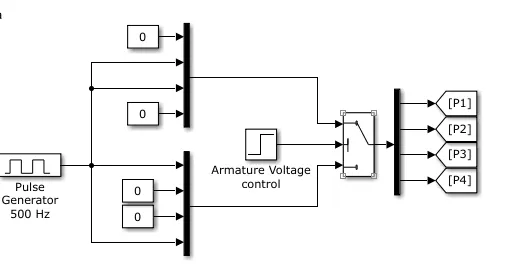
the control signals fot the switches are given from P1 P2 P3 P4
Which are in turn controlled by a pulse generator as shown in below
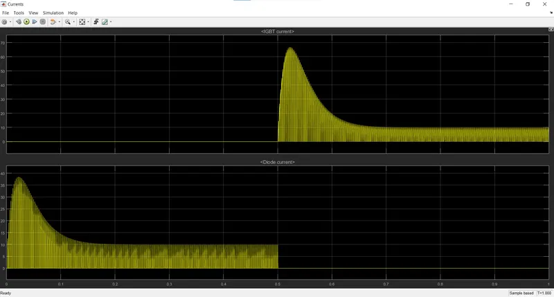
the IGBT and Diode currents are"
The speed and armature current and Load torque waveforms are:
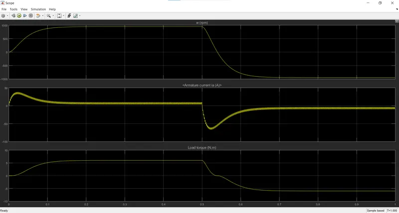
the speed is reached to 945 rpm in 0.145seconds.
and decelarates from 0.5 seconds. at 0.54 seconds the motor runs in backward.
ANSWER 1B:
The Speed and Armature current is obtained by the DC Motor and Load Torque is Calculated by load torque proportional to square of speed. In Starting point, there is a sudden Shootup is acted. In this Scope shows that speed is increased in certain period of Time and at that time armature current is positive whereas Load Torque also moves forward. After the time period of 0.5 sec which is given in Pulse generator (step time), sudden shoot-up is acted and speed gets decreased inthat time armature current is in negative terminal whereas Torque act as reverse action. Here the sudden shoot up is acted while Armature current is processed at a positive and negative terminal.
One simple and easy way to control the Speed of a Motor is to Regulate the Amount of Voltage across its Terminals and this can be achieved using "Pulse Width Modulation" (PWM Technique).
For Experimental Section we will reduce the Pulse width of Pulse generator block as 50% at the same time period.
The Inputs of P1, P2, P3 and P4 are also changed according to the drive cycle. When the Q1 and Q4 switch is ON the Motor is generated as Forward direction that state Q3 switch and Q2 switch is in OFF.
When the Q2 and Q3 switch is ON the Motor is generated as reverse direction that state Q1 and Q4 switch is in OFF Condition.
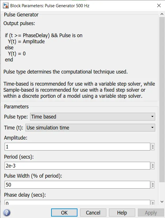
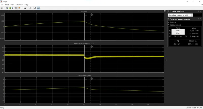
Here we see that the sudden shoot up is not acted by comparing with 75 of pulse width. Same cycle time is followed in this experiment also. In this observation starting current is generated as Diode current for time period of 0.5 sec, then IGBT current is acted while diode current is being stopped. This graph shows when the switch Q3 is OFF on the starting stage of current flow and Diode current is ON at that stage. During the 0.5 sec of time D3 switch is ON that is given according to the Pulse generator and after the time period of 0.5 sec D3 switch is OFF. An IGBT current is acted after 0.5sec and Q3 switch remains ON. There will be little variation as shown in graph at the starting point of current but the complete reduction of Shoot-Up are not held here.
ANSWER 1C:
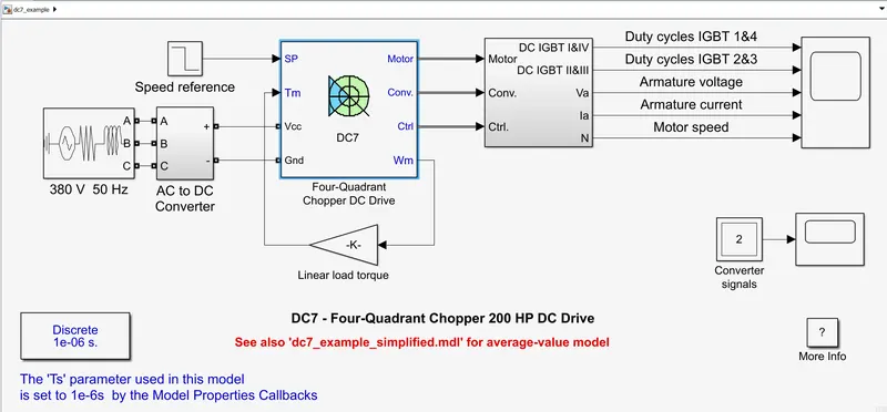
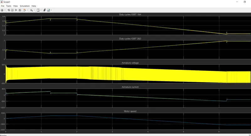
The Four-Quadrant Chopper DC Drive (DC7) block:
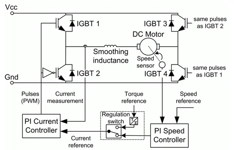
An Example of DC7 : 4 quadrant chopper 200HP DC DRIVE:
COMPARISION:
1. In four Quadrant Chopper DC drive distributes required current supply for each sector and it consist of 4 quadrants like Forward Motoring, Regenerative Braking, Reverse Motoring and Reverse Regenerative Braking. Whereas in H-bridge supplies an irregular current for each sector that causes voltage Fluctuation in armature current, it consist of 2 Operation namely they are Forward Motoring, Reverse Motoring.
2. In Modern Battery Technology Charger use for EV charging uses H-bridge circuit. Whereas a Four Quadrant Operation is required in Industrial as well as Commercial application.
3. The efficiency is high in Chopper compare with H-bridge and Maintenance is less than H-bridge.
4. In Robotic Technology, H-bridge circuit is used; some other application of Four Quadrant Operation is Engine Test Loading Systems.
5. In H-bridge we need to change Polarity which turns into opposite direction to control the motor whereas in chopper model we need to interrupt one signal under control of another.
| DC 7 four quadrant chopper | BJT H-Bridge Drive |
| It can be operated in 4 ways motoring and braking in both directions. | It is used for changing the direction of motor (forward&reverse). |
| Regenerative Braking can be Achieved. |
Regenerative Braking cannot be available. |
| the source is Ac supply which is rectified into DC supply. |
The source is fixed Dc supply |
| the motor ref. speed can be fed. | The motor speed reference cannot be fed |
| have comparatively less shoot up | the arm.current shoot up is possible |
| better control over the vehicle | less control over the vehicle |
| here signals are discrete | here signals are continuous |
ANSWER 2:
Modelling of two quadrant chopper:
here we are modelling Type - C chopper
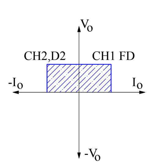
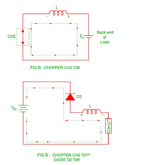
The type C chopper is parallel combination of type A and type B chopper. The output voltage is always positive but output current either positive or negative in this type of chopper therefore it works in first as well as second quadrant.
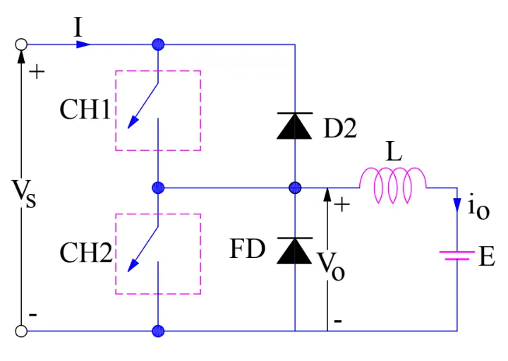
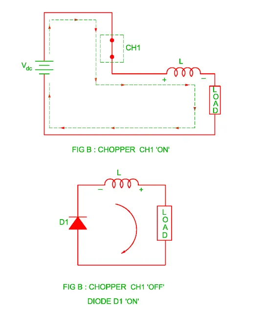
when ch1 is closed, the flow of current to the motor is shown in the below image,
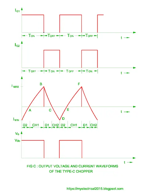
the wave forms are shown below
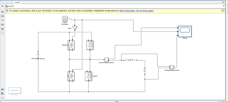
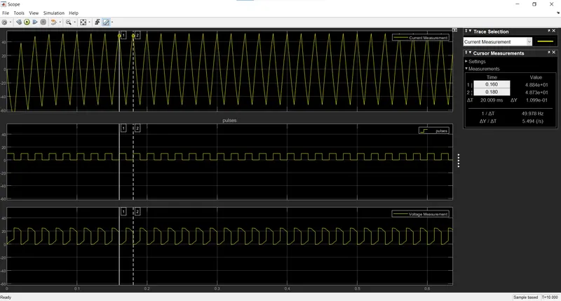
the gate currents are given from a pulse generator and using one not gate so that both mosfets will not triggered at a time.
reference:https://www.myelectrical2015.com/2017/03/type-c-chopper.html
ANSWER 3:
OPERATION OF BLDC MOTOR:
BLDC motor works on the principle Lorentz force law which states that whenever a current carrying conductor placed in a magnetic field it experiences a force. As a consequence of reaction force, the magnet will experience an equal and opposite force. In case BLDC motor, the current carrying conductor is stationary while the permanent magnet moves.
When the stator coils are electrically supplied by a source, it becomes electromagnet and starts producing the uniform field in the air gap. Though the source of supply is DC voltage, switching makes to generate an AC voltage waveform with trapezoidal shape. Due to the force of interaction between electromagnet stator and permanent magnet rotor, the rotor continues to rotate.
Consider the figure below in which motor stator is excited based on different switching states. With the switching of windings as High and Low signals, corresponding winding energized as North and South poles. The permanent magnet rotor with North and South poles align with stator poles causing motor to rotate.
here we can observe that motor produces torque because of the development of attraction forces (when North-South or South-North alignment) and repulsion forces (when North-North or South-South alignment). By this way motor moves in a clockwise direction.
The motor continuous rotation depends on the switching sequence around the coils. commutator and brush arrangement is eliminated in a brushless dc motor. And an integrated inverter/switching circuit is used to achieve unidirectional torque.