Week -2
1. Simulink model of a door bell using soleniod block.
Aim:
Create a situation where the switch is closed for 2 seconds and then released. Observe the physical movement of the plunger.
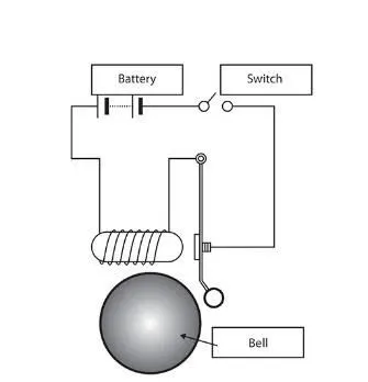
Explanation:
The principle used in the circuit to ring the bell is the electromagnetism. A solenoid is a long piece of wire which is wound in the shape of a coil. When the electric current passes through the coil it creates a relatively uniform magnetic field inside the coil. The name solenoid is derived from the Greek word “Solen” which means a channel or a pipe.
When the battery supplies power to the switch the contact is closed and the current flows through the solenoid producing the electromagnetic field around it. This field attracts the metal part of the plunger towards it as the result the arm attached to it hits the gong of the bell.
Conditions:
Switch On time = 2 secs and to observe the movement of the plunger.
Requirements:
- Pulse generator - Input
- Battery
- Switch
- Solenoid
- Ideal translational motion sensor
- Solver configuration and References (electrical and mechanical)
- Display and Scope - Output
Simulink model:
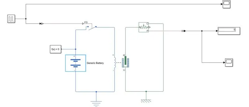
Fig-1
The model above represents the electric bell where the input is given as the pulse generator and the input parameters of the pulse generator is changed to achieve the given condition.
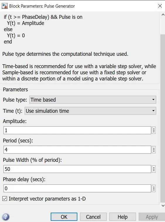
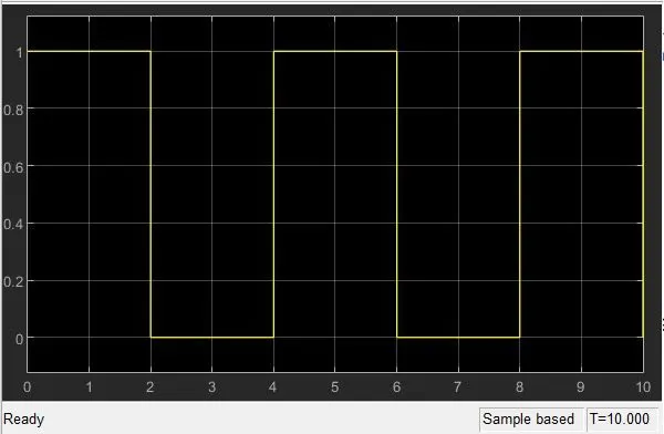
Fig-2 Fig-3
The Fig-2 shows the parameters altered to generate a pulse for a period of two seconds. The phase delay can be given as 0 or 2. When 0 is given there is no delay in the signal whereas when a delay of 2 is given then the signal wave is observed with a delay of 2 secs in the output. In the period 4 secs is given as the pulse On period is 2 seconds and the remaining 2 seconds it is Off. This is because the Pulse width is reduced to 50% of its initial value. The graph representing the input pulse signal is shown in Fig-3.
The connections are made as shown in the Fig-1. The solenoid block consist of a coil which is connected to the battery and switch in the electrical side and since the plunger movement is the mechanical motion it is connected with the ideal translational motion sensor to observe the output.
Output:
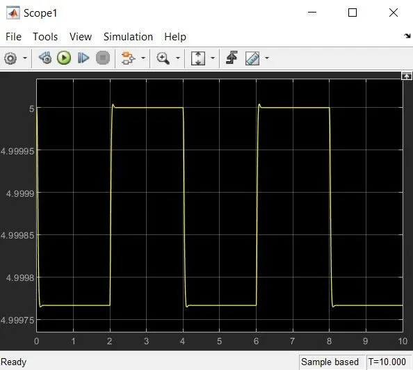
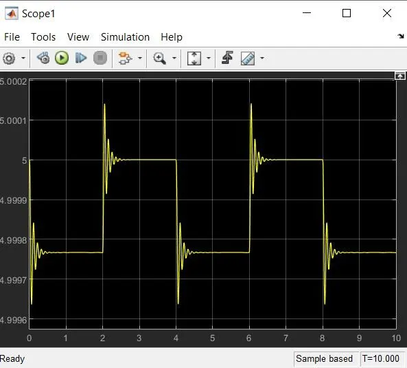
Fig-4 Fig-5
In the solenoid block the mechanical parameter damping is changed to 5 obtain a smooth output curve as shown in Fig-4. The damping can be as such the default value which is 1 then the output obtained (with no damping) can be viewed in Fig-5. The ideal translational motion sensors initial position can be adjusted based on the how we prefer to view the output. In this experiment it is fixed as 5. Since we did not provide a phase delay to the input graph’s initial position is at 5.
2. Use a thermistor to sense the temperature of a heater & turn on or turn off the fan
Condition:
|
Temperature (in celcius) |
Time (in secs) |
|
20 |
0-10 |
|
27 |
10-30 |
|
23 |
30-50 |
Thermistor: There are many types of resistors and almost all of them have slight fluctuation in their resistance due to temperature, but thermal resistors are particularly sensitive to temperature changes in which their electrical resistance is dependent on temperature. Thermistors are suitable choice for sensor based applications but do not work well in extreme conditions(too hot or too cold). Thermistors act as a passive component in a circuit. They are an accurate, cheap, and robust way to measure temperature. The commonly used type of thermistor is NTC(negative temperature co-efficient) thermistor, where temperature and resistance are inversely proportional.
Input :
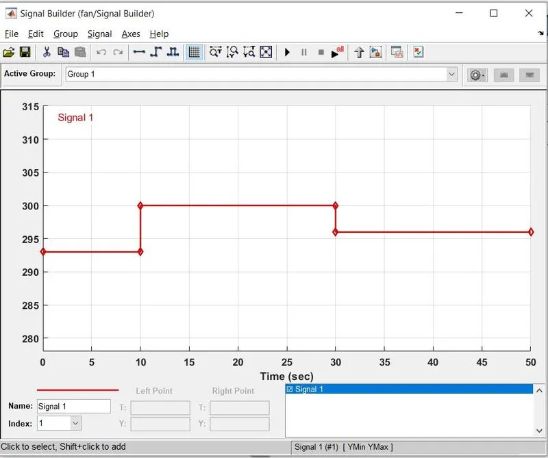
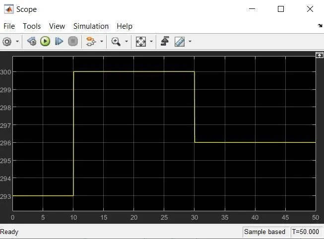
Fig-1 Fig-2
The input is given to the model using a signal builder as shown in Fig-1. This block helps us to generate the desired signal input when specific conditions are to be met. The graph for the input signal is shown in Fig-2.
Simulink model:
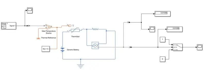
Fig-3
Aim:
Fan should be turned ON if the temperature above 25 °C, otherwise it should be turned off.
Requirements:
- Input – signal builder
- Ideal temperature source
- Thermistor
- Battery
- Resistor
- References (electrical and thermal) and solver configuration
- Voltage sensor
- Simulink PS- converter and PS- Simulink converter
- Switch
- Display and scope.
Explanation:
Using the signal builder the Condition for the input signal is built and fed to the controlled temperature source. The temperature is then sensed by the thermistor but it is difficult to find the temperature directly to turn on the fan. So a resistor is introduced in the circuit and the voltage across the resistor is measured at 25 degree Celsius and is given to the switch as its threshold value. Hence the switch is turned on when the value of the voltage goes higher than the threshold value i.e. 0.01099V. Hence when the voltage across the resistor goes above the threshold value of the switch the contact is closed and switch is turned ON and the output is observed from 10 to 30 secs as shown in the output graph.
Output:
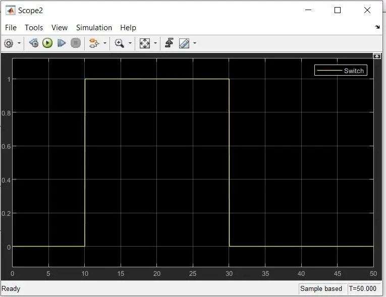
Fig-4
Fig-4 represents the output where the switch is turned on for 10 to 30 secs.
Final verdict:
The simulation for the electric door bell model and the thermistor to observe the temperature to turn on and off the fan is done and the output is viewed.
- For the door bell experiment the simulation was done for 10 seconds with the ON time of 2 seconds and the outputs with and without damping are shown in Fig-4 and Fig-5 respectively. A signal builder or pulse generator can be used for this experiment but the pulse generator is the preferable option.
- Since the thermal conditions for the thermistor is given the best option to provide the input signal is the signal builder block. Similarly the simulation is done of 10 seconds. As the threshold value is given to the switch it is turned on above that value and hence the signal is high only for the period of 10 to 30 seconds where the temperature is 27 degree Celsius over that period of time.