Week-7 Challenge: DC Motor Control
1. A. Explain a MATLAB demo model named ‘Speed control of a DC motor using BJT H-bridge’.
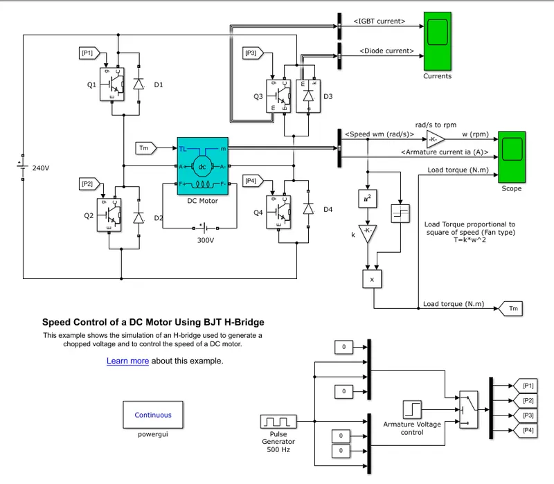
- H bridge used to generate a chopped voltage and control the speed for motor
- BJT-Bipolar Junction Transistor
- BJT conducting forward voltage (Vf) is developed between collector and emitter
- igbt blocks does not simulate the gate current controlling the BJT (or) IGBT
- DC motor - 5hp,24v,1750 rpm used . it is fan type load
- load torque directionally propotional to square of speed.
H BRIDGE:
- H bridge consist of four BJT/diode pairs
- Two transisitors are switched simultaneously Q1&Q4 or Q2&Q3
- Q1&Q4 are fixed a positive voltage applied to a motor and D2&D4 diodes are free wheeling diode when Q2&Q3 switched off
- Q2&Q3 are fixed a negative voltage apllied to a motor and D1&D4 diodes are free wheeling diode when Q1&Q4 switched off
SCOPE:
- Scope display a armature current,rpm,load torque and current shown in Q3 and D3
B. Comment on the armature current shoot-up from the scope results.
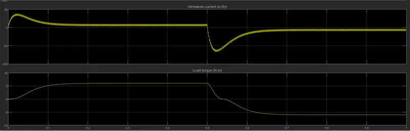
- this simulation have 1 sec and IGBT switched for 0.5 sec then armature current have positive direction for first .5 sec
- after 0.5 sec Q2&Q3 switches are activated then armature current have negative direction.
C. Refer to the help section of ‘The Four-Quadrant Chopper DC Drive (DC7) block’. Compare it with the H-bridge model
| s. no | description | H bridge |
four quardant chopper |
| 1 | motor | 5 hp,24v,1750rpm used. |
200hp,150v motor used. |
| 2 | voltage | Its generate a chopped voltage and voltage developed between collector & emitter |
armature voltage provided by IGBT controlled by two PI regulators |
| 3 | directions | operates in four direction, forward motoring, reverse motoring, forward braking , reverse braking. |
operates in two direction forward and reverse direction. |
| 4 | regenerative braking | regenerative braking is acheived |
regenerative braking is not possible. |
2 . Develop a 2-quadrant chopper using simulink & explain the working of the same with the relevant results
It is basically combination of first and second quadrant chopper
In first case CH1 is ON and D2 conducts whereas CH2 is ON and D1 conducts in second case
two quadrant type B or class D chopper
when both CH1 and CH2 simultaneously trigerred,V0=v and current flows.
when both CH1 and CH2 is turned OFF the load current continues flow in same direction through load D1 and D2 due to presence of inductance L.
voltage is positive but load current is positive or negative in two quadrant chopper.
matlab model :
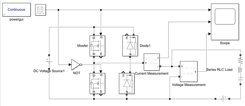
description :
- this model using a mosfet and diode pairs.
- voltage source connected in mosfet and g point receive a signal from pulse generator
- powergui block used in this model because measurement block are work properly
- series RLC load used
- voltage measured between postive of load and common
- scope diplaying the current,voltage and pulses
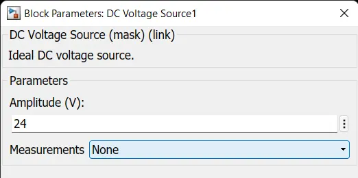
DC voltage source :
amplitude voltage set in 24 v and load side source is 12 v
pulse generator :
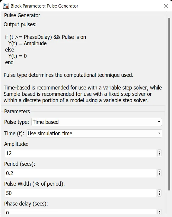
amplitude is 12 v and period is 0.2 sec phase width set as 50%
scope result :
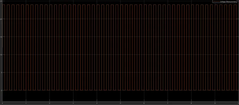
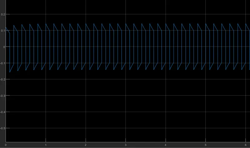
In two quadrant chopper voltage doesn't reach a negative value. when ch1 is ON voltage reach 24 v and ch1 turned off voltage reach 0 v but current flow is continues through diode.current value is > 0.1 when CH1 is ON then current reach >-0.1 when CH1 is OFF condition and current flows in diode.
RESULT :
two quadrant chopper mostly used in electric car for the purpose of forward motoring and braking .
in chopper using mosfet , it is used for low power operation.controlling the pulses acrossing the semiconductor device we can control the speed of the drive.
3. Explain in a brief about operation of BLDC motor.
A brushless DC motor (known as BLDC) is a permanent magnet synchronous electric motor which is driven by direct current electricity and it accomplishes electronically controlled commutation system (commutation is the process of producing rotational torque in the motor by changing phase currents through it at appropriate times) instead of a mechanically commutation system. BLDC motors are also referred as trapezoidal permanent magnet motors
CONSTRUCTION OF BLDC MOTOR :
BLDC motors can be constructed in different physical configurations. Depending on the stator windings, these can be configured as single-phase, two-phase, or three-phase motors. However, three-phase BLDC motors with permanent magnet rotor are most commonly used
rotor :
BLDC motor incorporates a permanent magnet in the rotor. The number of poles in the rotor can vary from 2 to 8 pole pairs with alternate south and north poles depending on the application requirement. In order to achieve maximum torque in the motor, the flux density of the material should be high. A proper magnetic material for the rotor is needed to produce required magnetic field density.
Ferrite magnets are inexpensive, however they have a low flux density for a given volume. Rare earth alloy magnets are commonly used for new designs. Some of these alloys are Samarium Cobalt (SmCo), Neodymium (Nd), and Ferrite and Boron (NdFeB). The rotor can be constructed with different core configurations such as the circular core with permanent magnet on the periphery, circular core with rectangular magnets, etc.
Working Principle and Operation of BLDC Motor
BLDC motor works on the principle similar to that of a conventional DC motor, i.e., the Lorentz force law which states that whenever a current carrying conductor placed in a magnetic field it experiences a force. As a consequence of reaction force, the magnet will experience an equal and opposite force. In case BLDC motor, the current carrying conductor is stationary while the permanent magnet moves.
When the stator coils are electrically switched by a supply source, it becomes electromagnet and starts producing the uniform field in the air gap. Though the source of supply is DC, switching makes to generate an AC voltage waveform with trapezoidal shape. Due to the force of interaction between electromagnet stator and permanent magnet rotor, the rotor continues to rotate.
Consider the figure below in which motor stator is excited based on different switching states. With the switching of windings as High and Low signals, corresponding winding energized as North and South poles. The permanent magnet rotor with North and South poles align with stator poles causing motor to rotate.
Observe that motor produces torque because of the development of attraction forces (when North-South or South-North alignment) and repulsion forces (when North-North or South-South alignment). By this way motor moves in a clockwise direction.
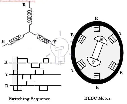
Here, one might get a question that how we know which stator coil should be energized and when to do. This is because; the motor continuous rotation depends on the switching sequence around the coils. As discussed above that Hall sensors give shaft position feedback to the electronic controller unit.
Based on this signal from sensor, the controller decides particular coils to energize. Hall-effect sensors generate Low and High level signals whenever rotor poles pass near to it. These signals determine the position of the shaft
Advantages of BLDC Motor
- Smaller motor geometry and lighter in weight than both brushed type DC and induction AC motors
- Long life as no inspection and maintenance is required for commutator system
- Higher dynamic response due to low inertia and carrying windings in the stator
- Less electromagnetic interference
- Quite operation (or low noise) due to absence of brushes
Disadvantages of Brushless Motor
- These motors are costly
- Electronic controller required control this motor is expensive
- Not much availability of many integrated electronic control solutions, especially for tiny BLDC motors
- Requires complex drive circuitry
- Need of additional sensors