Week-7 Challenge: DC Motor Control
A. Explain a MATLAB demo model named ‘Speed control of a DC motor using BJT H-bridge’.
B. Comment on the armature current shoot-up from the scope results.
C. Refer to the help section of ‘The Four-Quadrant Chopper DC Drive (DC7) block’. Compare it with the H-bridge model.
A. The Bipolar Junction Transistor (BJT) when used for power switching applications, operates as an IGBT. When it is conducting (BJT operating in the saturated region), a forward voltage Vf is developed between collector and emitter (in the range of 1 V). Therefore, the IGBT block can be used to model the BJT device.
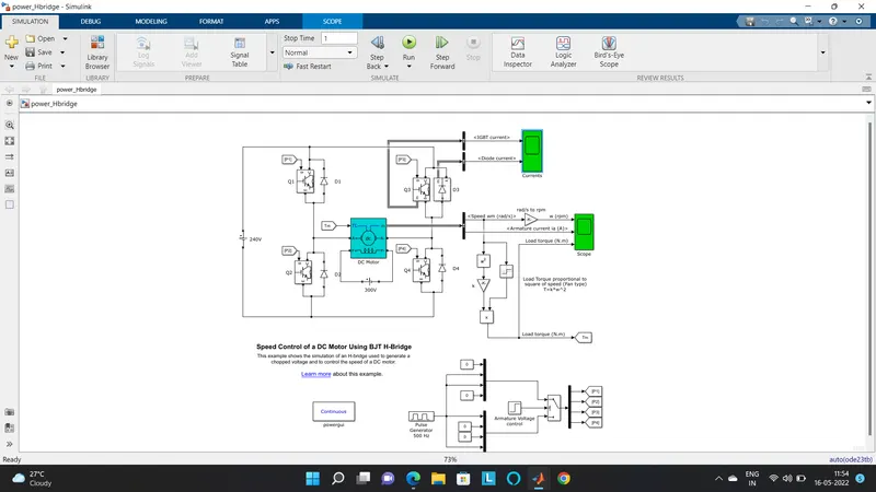
The IGBT block does not simulate the gate current controlling the BJT or IGBT. The switch is controlled by a Simulink® signal (1/0). The DC motor uses the preset model (5 HP 24V 1750 rpm). It simulates a fan type load (where Load torque is proportional to the square of speed). The armature means voltage can be varied from 0 to 240 V when the duty cycle (specified in the Pulse Generator block) is varied from 0 to 100%.
The H-bridge consists of four BJT/Diode pairs (BJT simulated by IGBT models). Two transistors are switched simultaneously: Q1 and Q4 or Q2 and Q3. When Q1 and Q4 are fired, a positive voltage is applied to the motor, and diodes D2-D3 operate as free-wheeling diodes when Q1 and Q4 are switched off. When Q2 and Q3 are fired, a negative voltage is applied to the motor, and diodes D1-D4 operate as free-wheeling diodes when Q2 and Q3 are switched off.
The motor starts in the positive direction with a duty cycle of 75% (mean DC voltage of 180V). At t= 0.5 sec., the armature voltage is suddenly reversed and the motor runs in the negative direction.
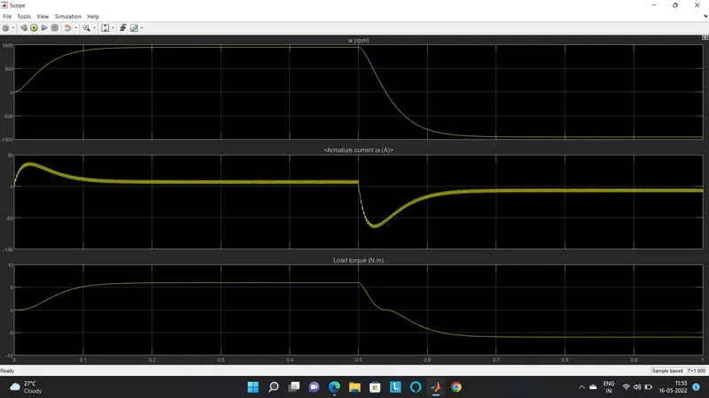
'Scope' shows motor speed, armature current, and load torque and 'Currents' shows currents flowing in BJT Q3 and diode D3.
B.
In motor, armature current (I) is given by:-
I=(V-E)/R.
Where, V is the voltage supplied, E is the back emf and R is the armature resistance.
Thus, I depend upon E and R when V is kept constant. When the motor starts its speed remains zero i. e E also remains zero(since back emf is ∝ the speed of the armature).
Thus, the initial starting armature current:-
I=(V-0)/R= V/R . (as, E =0)
Since the armature resistance of a motor is very small, generally less than one ohm, therefore the starting current would be very large.
This large current would damage the brushes, commutator, or windings. Also, it may damage supply installation.
As the motor speed increases, the back emf increases and the difference (V-E) goes on decreasing. This results in the gradual decrease of armature current until the motor attains its stable rated speed. Under this condition, the armature current reaches its desired rated value.
To avoid a high starting current an extra resistance must be connected in series with the armature. This external resistance is known as starter resistance. The series resistance is divided into sections which are cut out one by one as the speed of the motor increases and the back emf builds up. When the speed of the motor attains its normal value, the extra resistance is completely cut out.
C.
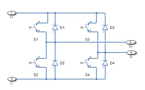
The block contains an integral protection diode for each switching device. The integral diode protects the semiconductor device by providing a conduction path for reverse current. An inductive load can produce a high reverse-voltage spike when the semiconductor device suddenly switches off the voltage supply to the load.
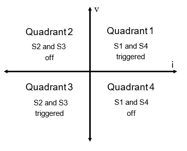
| FOUR QUADRANT CHOPPER CHARACTERISTICS | H-BRIDGE CHARACTERISTICS |
| 1. Regenerative braking is possible. | 1. Regenerative braking is not possible but dynamic braking can be achieved. |
| 2. The current values are chopped not continuous hence simulation takes less time. | 2. The current values are continuous. |
| 3. Widely used in automobiles to control DC motor speed and direction. | 3. Widely used in robotics and electro-mechanical devices to control DC motor speed and direction. |
| 4. To change the direction of motor current signals are interrupted with one another. | 4. To change the direction of the motor only the polarity of the current is changed |
2. Develop a 2-quadrant chopper using Simulink & explain the working of the same with the relevant results. (Refer to the article - Multiquadrant operation of the motor )
What is a chopper?
A dc-to-dc converter, also known as a de chopper, is a static device which is used to obtain a variable de voltage from a constant dc voltage source. Choppers are widely used in trolley cars, battery-operated vehicles, traction motor control, control of large numbers of dc motors, etc. They are also used as de voltage regulators. Choppers are of two types: (1) Step-down choppers, and (2) Step-up choppers. In step-down choppers, the output voltage will be less than the input voltage, whereas in step-up choppers output voltage will be more than the input voltage
Open Simulinkand build a 2 quadrant chopper as shown below
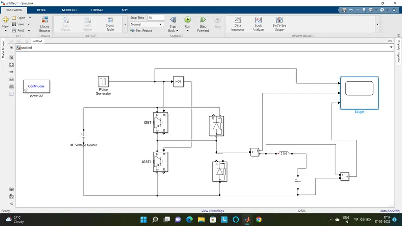
Two Quadrant Chopper
In this type of Chopper, the average voltage will be always positive but the average load current might be positive or
negative. The two Switches IGBT1 and IGBT2 should not be turned on simultaneously as the combined action may cause a short circuit in supply lines. For regenerative braking and motoring these type of chopper configuration is used. We will always get a positive output voltage Vo as the freewheeling diode FD is present across the load. When the chopper IGBT1 is on the current flows from source to load. The inductor stores energy. When IGBT1 turns OFF the freewheeling diode starts conducting and the output voltage vo will be equal to Vs. The direction of the load current io will be reversed. The current will be flowing towards the source. The load current will be negative when the IGBT2 is on. The current completes its path through diode D2.
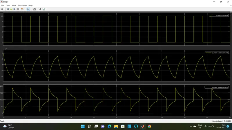
First Quadrant Operation:
For the first quadrant operation, IGBT1 is kept ON, IGBT2 is kept OFF and IGBT1 is operated. When both IGBT1 & IGBT2 are ON simultaneously, the source will get short-circuited, and hence they shouldn't be ON simultaneously. This essentially means that the triggering pulse should be to one IGBT at a time. It may be noted that the load current flows from source to load as shown by the direction of lo. When IGBT1 is switched OFF, the load current freewheels through Diode2. During this period, the load voltage and current remain positive. Thus, both the output voltage and load current io are positive, and hence, the operation of the chopper is in the first quadrant. It may be noted that the Class F chopper operates as a step-down chopper in this case.
Second Quadrant Operation:
To obtain second quadrant operation, IGBT2 is operated while keeping the OFF. When IGBT2 is ON, the DC source in the load drives current through IGBT2, E, and L. Inductor L stores energy during the on period of IGBT2. When IGBT2 is turned OFF, the current is fed back to the source through Diode1. It should be noted at this point that (E+Ldi/dt) is more than the source voltage Vs. As load voltage Vo is positive and lo is negative, it is the second quadrant operation of the chopper. Since the current is fed back to the source, this simply means that load is transferring power to the source.
3. Explain in a brief about the operation of the BLDC motor.
A Brushless DC motor or BLDC motor is the type that is most suitable for applications that require high reliability, high efficiency, more torque per weight, etc.
Construction Of A BLDC Motor
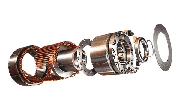
Just like any other electric motor, a BLDC motor also has a stator and a rotor. Permanent magnets are mounted on the rotor of a BLDC motor, and the stator is wound with a specific number of poles. This is the basic constructional difference between a brushless motor and a typical dc motor.
Working Principle Of A BLDC Motor
Stator windings of a BLDC motor are connected to a control circuit (an integrated switching circuit). The control circuit energizes proper winding at the proper time, in a pattern that rotates around the stator. The rotor magnet tries to align with the energized electromagnet of the stator, and as soon as it aligns, the next electromagnet is energized. Thus the rotor keeps running. The commutator helps in achieving unidirectional torque in a typical dc motor. Commutator and brush arrangement are eliminated in a brushless dc motor. And an integrated inverter/switching circuit is used to achieve unidirectional torque.
That is why these motors are, sometimes, also referred to as ‘electronically commutated motors.
BLDC Motor operation is based on the attraction or repulsion between magnetic poles. Using the three-phase motor. The process starts when the current flows through one of the three stator windings and generates a magnetic pole that attracts the closest permanent magnet of the opposite pole. The rotor will move if the current shifts to an adjacent winding. Sequentially charging each winding will cause the rotor to follow in a rotating field. The torque in this example depends on the current amplitude and the number of turns on the stator windings, the strength and the size of the permanent magnets, the air gap between the rotor and the windings, and the length of the rotating arm.
A typical brushless motor has permanent magnets that rotate around a fixed armature, eliminating problems associated with connecting current to the moving armature. An electronic controller replaces the commutator assembly of the brushed DC motor, which continually switches the phase to the windings to keep the motor turning. The controller performs similar timed power distribution by using a solid-state circuit rather than the commutator system. Brushless motors offer several advantages over brushed DC motors, including high torque to weight ratio, increased efficiency producing more torque per watt, increased reliability, reduced noise, longer lifetime by eliminating brush and commutator erosion, elimination of ionizing sparks from the commutator, and an overall reduction of electromagnetic interference(EMI). With no windings on the rotor, they are not subjected to centrifugal forces, and because the windings are supported by the housing, they can be cooled by conduction, requiring no airflow inside the motor for cooling. This in turn means that the motor's internals can be entirely enclosed and protected from dirt or other foreign matter.
Brushless motor commutation can be implemented in software using a microcontroller, or may alternatively be implemented using analog or digital circuits. Commutation with electronics instead of brushes allows for greater flexibility and capabilities not available with brushed DC motors, including speed limiting, micro-stepping operation for slow and fine motion control, and a holding torque when stationary. Controller software can be customized to the specific motor being used in the application, resulting in greater commutation efficiency. The maximum power that can be applied to a brushless motor is limited almost exclusively by the heat too much heat weakens the magnets and will damage the windings' insulation. When converting electricity into mechanical power, brushless motors are more efficient than brushed motors primarily due to the absence of brushes, which reduces mechanical energy loss due to friction. The enhanced efficiency is greatest in the no-load and low-load regions of the motor's performance curve