Week-6 Challenge: EV Drivetrain
1.Which types of power converter circuits are employed in electric and hybrid electric vehicle?
There are 4 main categories of power converter circuits which are used in electric and hybrid electric vehicles.
AC TO DC CONVERTER
This type of converter takes an input AC power supply and converts it to DC one.Power generated from a power plant is delivered to our homes at a voltage of 230v at a frequency of 50Hz which we can use to power our electrical appliances.But some of our appliances operate on a DC supply,not on a AC, SO we need a converter for this application.
Examples of AC to DC converter : mobile charger , laptop charger etc
In the case of EV's or HEV's,the battery pack which operates with a DC power supply is charged at home or at a charging station both of which are supplied power in AC form from the electric grid.So, the chargers for these vehicles are an example of the AC to DC power converter.
DC TO AC CONVERTER
This type of converter takes a DC supply and converts it to an AC one.Power which is supplied from a battery or capacitor can have its form changed to the AC type for use in homes or systems which have an AC load.For instance, the power generated by solar panels are stored in batteries in the DC form and this can power a house which uses an AC power supply so that we can utilise this power from the mains.This type of converter is referred to as an 'inverter' and is widely used in homes and in EV/HEVs.
The DC supply is changed to an AC waveform using an electronic switch, which is basically a set of semiconductor transistors E.g. IGBTs,MOSFETs.These switches are contrlolled by a controller to either be in an open or closed position to direct the flow of current in a circuit.The controller sends signals to the switches to tell it to open/close, and even decides the frequency for the same.By doing this operation, the DC current mimics an AC current and can be fed to the load which requires it.
In the case of EVs & HEVs, the battery pack will supply its power to the inverter. The inverter contains a transformer which consists of a primary and secondary winding.The current from the battery is first supplied to the primary winding where the electronic switches will repeatedly reverse the direction of the current will return back the way it came from.The AC current in the primary winding will induce an AC current in the secondary winding which then supplies this current to an AC load e.g. the AC traction motor.
DC TO DC CONVERTER
This type of converter is similar to a transformer in that it can change the voltage from its current level to another level.It can take an input supply of voltage and increase it or do the exact opposite and decrease it , similar to a step up or step down transformer.This kind of converter is called a 'chopper'.The purpose of using this type of converter is to provide the necessary level of power to a particular component and for the safety of the appliance and the user.If a component is supplied with too little or too much voltage,It can't operate properly due to lack of power or it will get damaged.
It works by taking the DC supply and passing it through a switching element which converts the waveform to a square wave which is actually AC in nature. Then this AC is passed through a filter which will will turn it back in to a DC supply for use in a load. In EVS, HEVS and conventional vehicles, this type of converter is used for various purposes. E.g. In the case of stepping down the voltage, the car radio may require a stepped down voltage of 12V to operate and would not need the full voltage of the car battery. In the case of stepping up the voltage, the motor of a car may require 500V to operate, but the vehicle may need more voltage than the battery pack can provide.
There are two types of DC to DC converters which are isolated & non-isolated .The non-isolated is subdivided into 5types:
*BUCK - to step down the voltage
*BOOST - to step up the voltage
*BUCK/BOOST - this can do both step down & step up the voltage
*CUK - similar to the buck/boost type
*CHARGE PUMP - to step up/step down the voltage for low power sources
The isolated type can be subdivided into 2 types:
*FLYBACK CONVERTER - similar to the buck boost converter except it uses a transformer instead of an inductor to store energy
*FORWARD CONVERTER - this type will use a transformer to send energy between the input and output in a single step.
AC TO AC CONVERTERS
This type of converter takes an input AC waveform with a particular voltage and frquency and outputs a different AC waveform with another voltage and frequency.The output voltage and frequency can be changed or maintained depending on the application.This converter has many applications in our daily life e.g. lamp dimming,motor speed control etc. There are 4 main types of AC to AC converters
*Cycloconverters
This type is also known as a frequency changer as it will change the frequency of an input AC waveform and output an AC waveform with another frequency but it can also change the magnitude of the power. This type of converter does not have any DC linkages and avoids any conversion between AC and DC to prevent losses and save costs. The input wave's frequency is changed by changing the firing angle applied to a thyristor. By switching the positive and negative limb thyistors, we can get an output waveform that has a stepped up/down frequency compared to the input.
*Ac to Ac converter with Dc link
As the name suggests, this type includes a DC link along with a rectifier and an inverter. The input AC waveform is first rectified by the rectifier to remove the negative portions of the AC wave and output only the positive portions. This creates a DC waveform which is then stored in the DC link and is then converted back to an AC waveform using the inverter.
*Matrix converter
This type converts from AC to AC directly without using a DC linkage to reduce costs and losses that would otherwise be incurred with a DC link storage element. It is used mainly to increase the reliability and efficiency of a system. Matrix converters use bidirectional switches (IGBTS) to conduct current and block voltages of both polarities.
*Hybrid matrix converter
This type is very similar to the matrix converter in that they combine the AC//DC/AC design with the matrix design. It uses unidirectional switches and 2 converter stages, without the DC link to reduce the size and weight of the converter.
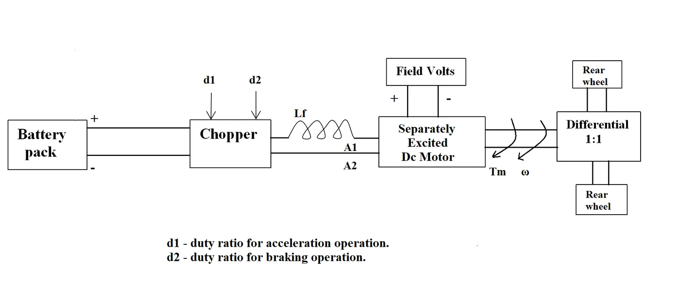
2. An Electric Vehicle's powertrain with 72V battery pack in shown in the diagram below. The duty ratio for acceleration operation is 'd1' and for the braking operation the duty ratio is 'd2'.
The other parameters of the electric vehicle is given below,
Motor and Controller Parameters:
Rated Armature voltage= 72 V
Rated armature current= 400 A
Ra= 0.5Ω, KΦ= 0.7 Volt second
Chopper Switching frequency= 400 Hz
The vehicle speed-torque characteristics are given by the below equation

What is EV steady state speed if duty cycle is 70%?
As the torque formula is given,we need to find the speed in rad/sec.Use the other expression available which is given below:
T = (V.k/R)-(K^2.W/R)
T = torque
V = armature voltage
R = resistance
w = speed rad/sec
compare the two equations:
24.7+0.00051*w^2 = ()v*k)/R)-((k^2)*w/R)
24.7+0.0051*w^2 = (72*0.7*0.7)/0.5-(0.7^2/0.5)*w
24.7+0.0051*w^2 = 70.56-0.98*w = 24.7 + 0.0051*w^2
w^2 + 192.15*w-8992.15 = 0
In order to find the roots use following formula
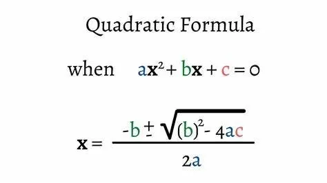
As the speed value can not be negative w = 38.95rad/sec
Q. Explain in brief about author’s perspective.
In the blog of induction and DC brushless motor, the author has mentioned about positives and negative side of both the induction and DC brushless motor is explained.
In case of brushless DC motor, permanent magnets are used which produces a rotating magnetic field.This magnetic field when induces a current in the conductor.This current results in rotation of the rotor.whereas in case of induction motor, the current is supplied to the stator induces a rotating magnetic field in the stator which cuts with the rotor conducting bars which are shorted at both ends, so an emf induces in them which results in the current to flow in them which will produce magnetic field around, so the reaction between the both magnetic fields produce a torque on the rotor.
One of the main difference is that the heat generated in the DC brushless motor is less compared to AC induction motor & the DC brushless motors can be driven at unity power factor where as the AC induction motors can't.In case of DC brushless motors, the field strength can be controlled whereas induction motor can't. As in the case of brushless DC motor losses increases as the size of the machine increases but in induction motors losses do not grow necessarily grow.
The construction of DC brushless motor is costly as compared to induction motors. However the speed variation of induction motor is depends on input frequency which is difficult/costlier to control.
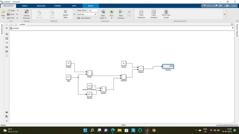
Q. Develop a mathematical model of a DC Motor for the below equation using Simulink.
ω = V/Kϕ -Ra/Kϕ^2 .T
AS
Rated Armature voltage= 72 V
Ra= 0.5Ω, KΦ= 0.7 Volt second
= 32.43