Week - 4
WASHING MACHINE USING STATEFLOW
AIM : Implement control logic of washing machine using state flow by giving certain conditions as per power input & water input, machine operates and obtain the output by lamp light
OBJECTIVE : To implement control logic of washing machine using stateflow as per given
*If the power supply is available, the system gets activated.If not then the process will stop and indicate by LED
* soaking time should be 200secs followed by washing time of 100secs
*The rinising happens for next 20secs and dryer runs for next 50secs
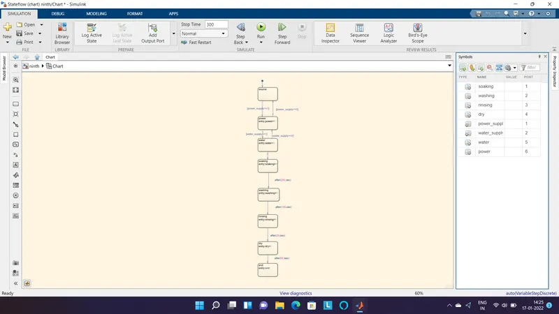
In the above control logic first junction is created with 2 conditions for power supply, one is when power supply is available (power supply > 0) and second without power supply (power supply == 0). If the power supply at the entry level is 1 or ON - the machine will get activated and start the next process. Next 2 power supply state is created with 2 states with one for if Power ON (power = 1) & another for power OFF (power= 0).After the power supply state next was to select the state for water Two water supply states are created with 2 states one for if water supply is on (water =1) applicable when (water supply > 0) & another for water supply OFF (water = 0) when (water ==0). Next 4 operation states have been created in flow order soaking, washing, rinsing, drying with their time of operation as 200 sec for a soak, 100 sec for wash, 20 sec for rinse & 50 sec for Entry and exit conditions of the states are kept as 1 because of the continuous operations of the process of the washing machine. These lamp blocks are connected to their respective output port in the chart. When the operation/process is ON it is represented by green colour indication in a lamp when the output is 1 and vice - a - versa for OFF is indicated by red colour when output is 0.
RESULT :
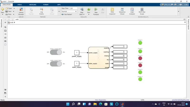
Here the time selected is 300secs thats why the operation ended at washing.
GEAR SHIFT LOGIC
AIM : Create the stateflow for gear shift & vary the speed as input and obtain the output as gear number as per below conditions
speed range gear
0 to 15 1
15 to 25 2
25 to 40 3
40 to 60 4
60 & above 5
EXPLINATION :
Create a chart block for defining the stateflow as per the given. If speed is less than or equal to 0, the flow is terminated and gear 0 is at the junction else 1 is carry forwarded. If speed is greater than 0 and less than or equal to 15, the flow is terminated and gear 1 is. If speed is greater than 15 and less than or equal to 25, the flow is terminated and gear 2 is. speed is greater than 25 and less than or equal to 40, the flow is terminated and gear 3 is. speed is greater than 40 and less than or equal to 60, the flow is terminated and gear 4 is. speed is greater than 60, the flow is terminated and gear 5 is
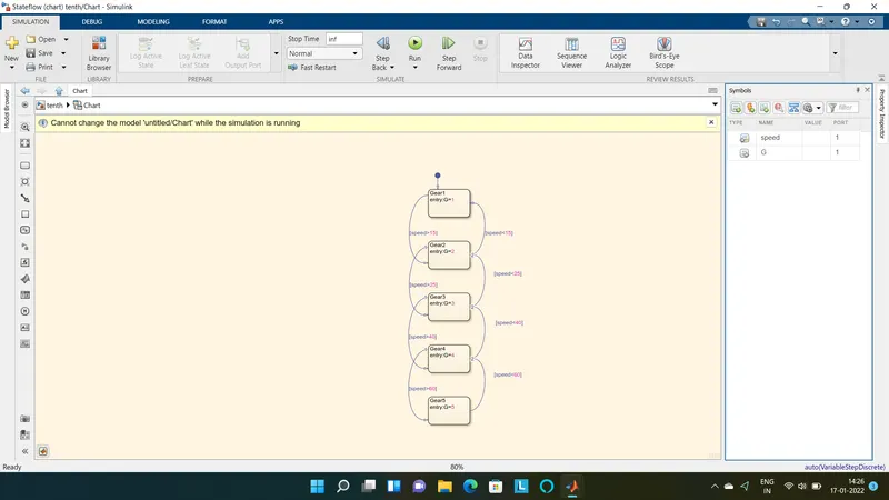
In the above logic control first - the default transition is dragged from the browser menu.
Five gear state is created with the state condition of Gear (G) 1,2,3,4,5 respectively and their transition is connected with speed range condition. The transition conditions for gear shift is decided as
speed > 15 shift to G = 2
speed > 25 shift to G = 3
Speed 40 shift to G = 4
Speed > 60 shift G = 5 (When the speed is increasing from 0 - 60 kmph)
Similarly in reverse direction Speed < 60 shift to G = 4
Speed <40 shift to G =3
Speed 25 Shift to G = 2
Speed < 15 Shift to G = 1 (when the speed is decreasing from 60 -0 kmph)
HERE SPEED IS AN INPUT CONDITION AND G IS AN OUTPUT CONDITION
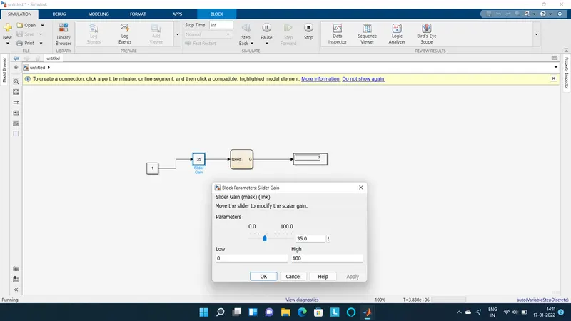
A constant block is connected with slider gain block to provide initial input. Slider gain block is used to define the speed slider to change the speed during simulation is running and it acts as input for speed. The output port (G) is connected with the Display to indicate the current gear for current speed in the slider gain.
RESULT : Hence the given problem was simulated for the gear shift meechanism and executing the statefllow a per the given conditions.