Week-7 Challenge: DC Motor Control
Student of EV Batch-16:
1(A)MATLAB demo model named ‘Speed control of a DC motor using BJT H-bridge’.
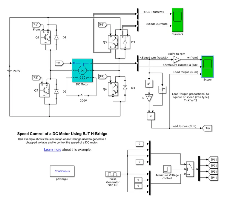
>Bipolar Junction Transistor(BJT) when used for power switching applications, operates as an IGBT. When it is conducting,a forward voltage Vf is developed between collector and emitter(in the range of 1V). Therefore, the IGBT block can be used to model the BJT device.
>The IGBT block does not simulate the gate current controlling the BJT or IGBT. The switch is controlled by a simulink signal(1/0). The DC motor uses the present model(5 HP 24V 1750 rpm). It simulates a fan type load
>The armature mean voltage can be varied from 0 to 240v when the duty cycle(specified in the pulse Generator Block) is varied from 0 to 100 %.
>The H-Bridge consists of four BJT/Diode pairs(BJT simulated by IGBT models).
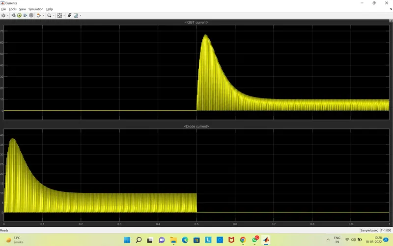
>Two transistors are switched simountenously:Q1 and Q4 or Q2 or Q3. When Q1 and Q4 are fired, a positive voltage is applied to motor and diodes D2-D3 operstes as free-wheeling diodes when Q1 and Q4 are switched off. When Q2 and Q3 are fired, a negative voltage is applied to the motor and diodes D1-D4 operate as free-wheeling diodes when Q2 and Q3 are switched off.
>Two scope blocks are used to display the output graph coming after running down the simulation.
1(B). Comment on the armature current shoot-up from the scope results.
Pulse Generator Parameters:
Period 2 Milliseconds
Pulse width (% of period) 75%
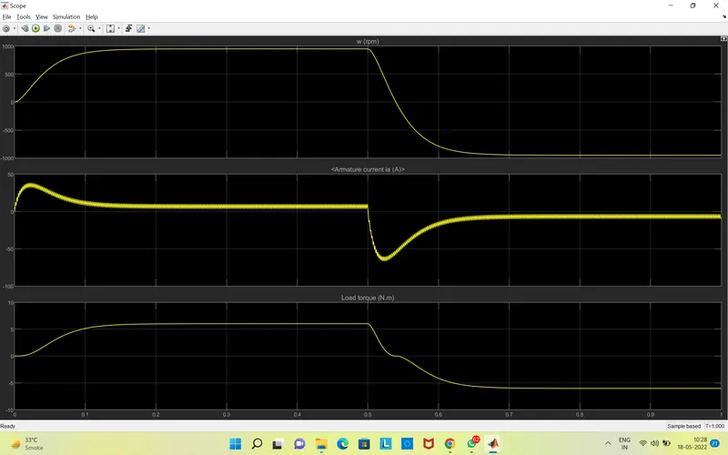
>Initally, there is a spike in armaure current.
>This is because, in a DC motor, Ia=(V-Eb)/Ra where,
Ia=armature current,
V=Voltage Supply,
Eb=Back emf,
Ra=Armature Resistance
>Therefore, Ia=V/Ra and Ra is a very small value.
>Hence Ia is huge and that reflects in the graph.
>Therefore, when pulse width decreases, the voltage applied across the DC motor decreases and the armature current finally decreases.
1(C)
The Four-Quadrant Chopper DC Drive (DC7) block
>The Four-Quadrant Chopper DC Drive (DC7) block represents a four-quadrant, DC-supplied, chopper (or DC-DC PWM converter) drive for DC motors.
>This drive features closed-loop speed control with four-quadrant operation. The speed control loop outputs the reference armature current of the machine. Using a PI current controller, the chopper duty cycle corresponding to the commanded armature current is derived.
>This duty cycle is then compared with a sawtooth carrier signal to obtain the required PWM signals for the chopper.
>The main advantage of this drive, compared with other DC drives, is that it can operate in all four quadrants (forward motoring, reverse regeneration, reverse motoring, and forward regeneration). In addition, due to the use of high switching frequency DC-DC converters, a lower armature current ripple (compared with thyristor-based DC drives) is obtained.
>However, four switching devices are required, which increases the complexity of the drive system.
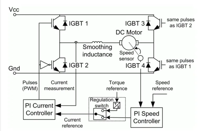
The Four-Quadrant Chopper DC Drive block uses these blocks:
Speed Controller (DC)
Regulation Switch
Current Controller (DC)
Chopper
Comparission Between H Bridge and Four Quadrant Chopper DC drive
H Bridge 4 Quadrant Chopper DC Drive
Only two quadrants of operations are possible. It can operate in all 4 quadrants.
It has higher armatyure current ripple. It has lower armature current ripple.
It's less complex. It's more complex.
Simulation time is more and process is more Simulation takes less time and process is
continous. discrete.
It's widely used in Robotics. It's widely used in automobile.
(2)
Working of 2 Quadrant chopper:
>Class-C or type-C is a category of chopper which can operate in first as well as second quadrant.
>This basically means that, the power can either flow from souce to load or load to source in this chopper.
>This kind of chopper s alos known as Two-Quadrant Class-A chopper.
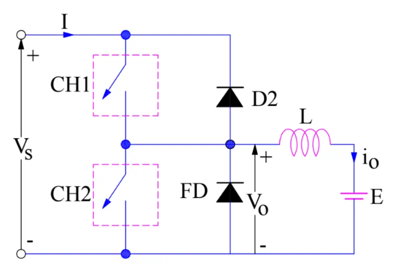
>If we connect Class A and Class B chopper, both these types of chopper in parellel then it is possible to have a chopper operation in first as well as second quadrant.
>In fact, Class-C or Type-C chopper is obtained by the parellle connection of class-A and class-B chopper.
>The above figue shows the circuit diagram of this type of chopper.
Simulink Model:
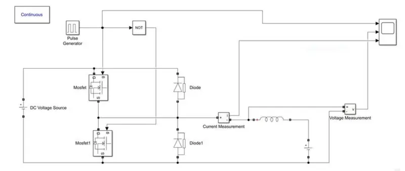
>Here the simulink model corresponding to the circuit diagram is built using basic simulink bocks.
>The pulse generator is used with the NOT gate to prevent misfiring of the MOSFETs so that they do not conduct at the same time which results in the short circuit.
Pulse Generator Parameters:
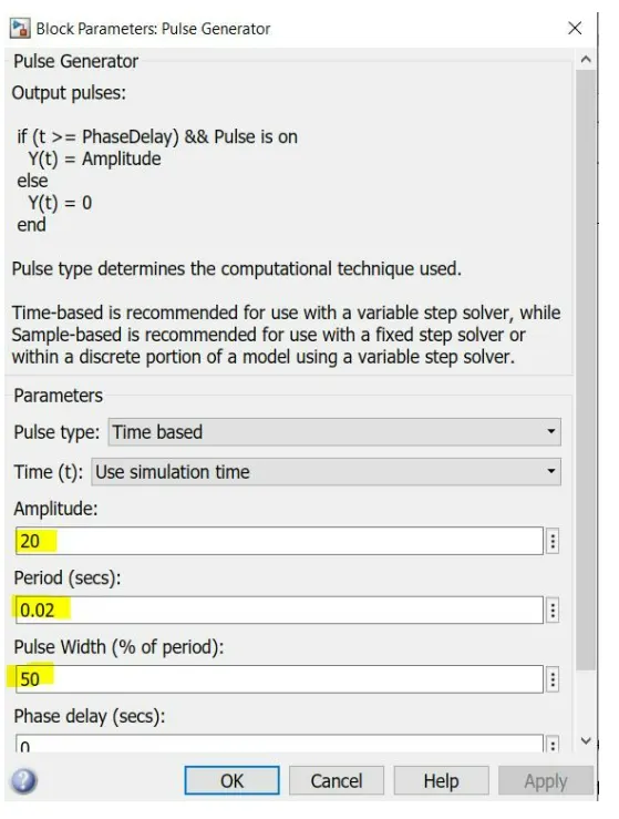
>An amplitude of 20 is chosen so that we could see the pulses clearly.
DC Voltage Source Paramters:
Source side: 24V
Load Side: 12V
Simulink Output:

>We can clearly see that the voltage is always positive but, the current becomes both positive and negative.
>Hence, the Two quadrant chopper is simulated and verified.
(3)Explain in a brief about operation of BLDC motor.
Construction:
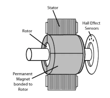
>In this motor, the permannent magnets are attached to the rotor.
>The current carrying conductors or armature windings are located on the stator.
>They use electrical communication to convert electrical energy into mechanical energy.
>The main design differnece between a brushed and brushless motors is the replacement of mechanical commutator with an electric switch circuit.
>A BLDC motor isa type of synchronous motor in the sense that the magnetic field generated by the stator and the rotor revolve at the same frequency.
Working:
>Brushless DC electric motors also known as commutated electrically motors(ECM, EC motors), works on a principle similar to Brushed DC motor.
>The Lorentz force law which states that whenever a current a current carrying conductor places in a magnetic field, it experinces a force.
>As a consequence of reaction of force, the magnet will exprince an equal and opposite force.
>In the BLDC motor, the current carrying conductor is stationary and the permanent magnet is moving.
>When the statot coil gets a supply from source, it becomes electromagnet and starts producing the uniform field in the air gap.
>Though the source of supply is DC, switching makes to genertae an AC volatge waveform with trapezoidal shape.
>Due to force of interaction between electromagnet stator and permanent magnet rotor, the rotor continues to rotate.
>With the switching of windings as HIgh and Low signals, corresponding winding energized as North and South poles.
>The permanent magnet rotor with North and South poles align with stator poles which causes the motor to rotate.