Week-7 Challenge: DC Motor Control
Objective: To provide appropriate solutions to the following questions,
- Run MATLAB demo ‘Speed control of a DC motor using BJT H-bridge’. Modify the model such that the armature current doesn’t shoot up when the motor changes direction from forward to reverse.
- Refer to the help section of ‘The Four-Quadrant Chopper DC Drive (DC7) block’. Compare it with the H-bridge model.
- Make a suitable EV model using the DC7 block and make a result report.
Explanation:
1. Speed control of a DC motor using BJT H-bridge
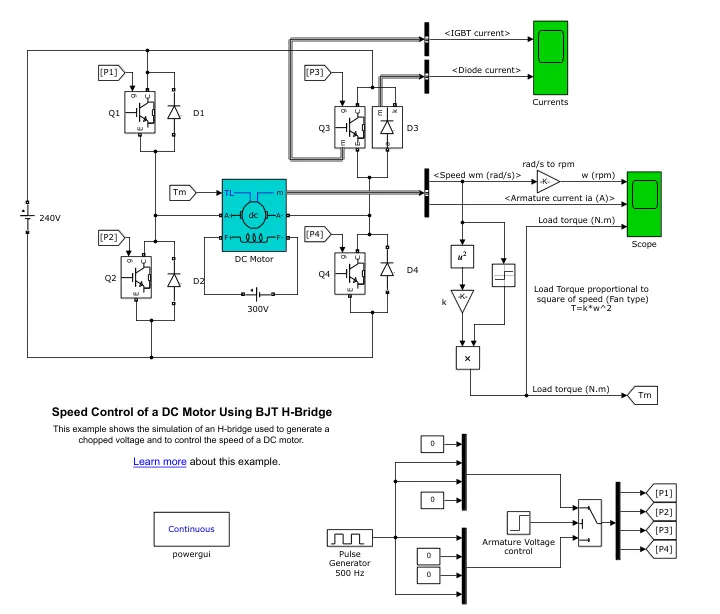
The Bipolar Junction Transistor (BJT) when used for power switching application operates as IGBT (Insulated Gate Bipolar Transistor). When it is conducting (BJT is operated in the saturated reigon) a forward voltage Vf is devloped between the collector and emitter(in the range of 1V). Therefore the IGBT block can be used to model the BJT device.The IGBT block does not simulate the gate current controlling the BJT or IGBT. The switch is controlled by the Simulink signal (1/0). The DC motor uses the present model (5 HP, 24 V, 1750 rpm). It simulates the fan type load (where Load torque is proportional to the square of speed). The armature mean voltage can be varied from 0 to 240 V when duty cycle (specified in Pulsed Generator Block) is varied from 0 to 100%.
The H-Bridge consists of 4 BJT/Diode pairs (BJT simulated by IGBT models). 2 transistors are switched simultaneously. When Q1 & Q4 a positive volatge is applied to the motor and diodes D2 & D3 are freewheeling diodes when Q1 and Q4 are switched off. When Q2 and Q3 are fired, a negative voltage is applied to motor and diodes D1 & D4 operate as free wheeling diodes when Q2 & Q3 are switched off.
The initial simulation obtained as shown below, is obtained by motor rotating in the positive direction with a duty cycle of 75% (mean DC voltage of 180V). At t=0.5 sec, the armature voltage is suddenly reversed and the motor runs in the negative direction.
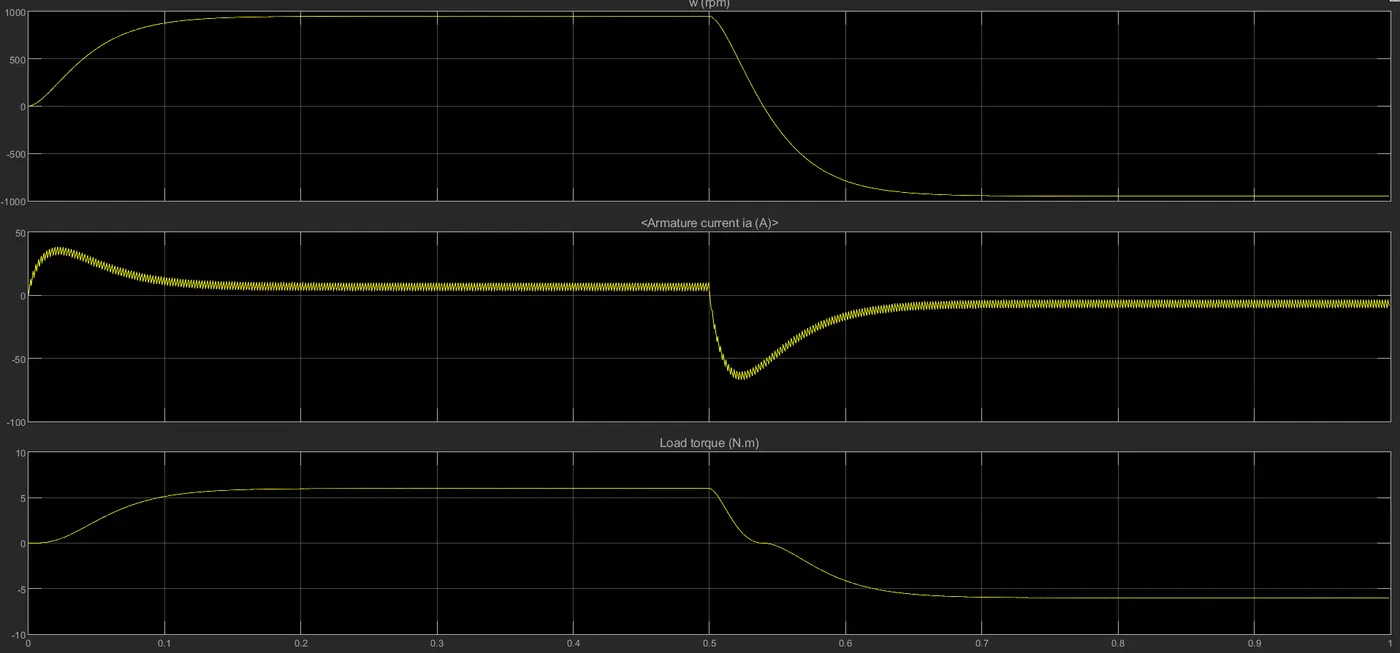
As stated in the question, there is shoot up in the armature current by 0.53-0.54 seconds. This drop in the armature current at 0.5 seconds is due to negative voltage (ie reverse motoring).
We know that during reverse motoring, the current, voltage and Torque goes negative and the back EMF alone goes positive. (since Back EMF is directly proportional to the voltage but with equal & opposite magnitude)
so this drop in armature current can be sorted out by reducing the duty cycle from 75% to 50%.
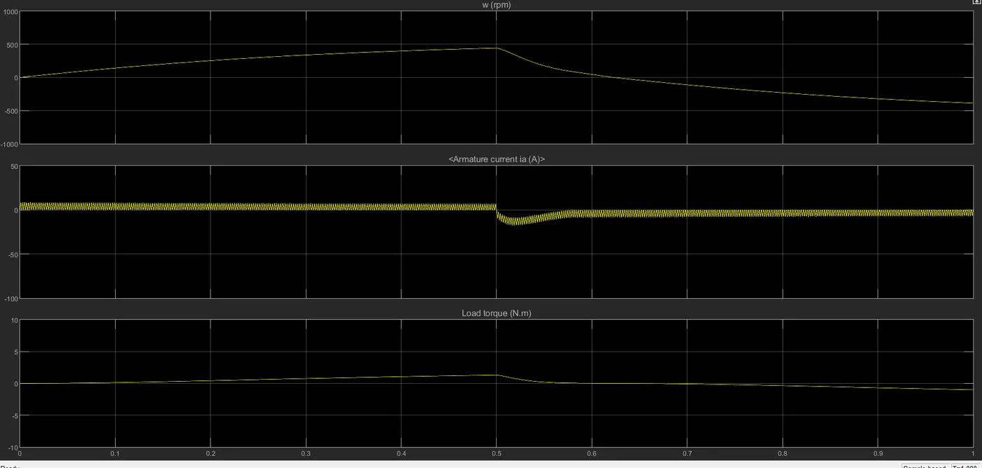
As we observe from the above graph, the Armatur current in the first case where maximum was around 45A by 0.05 seconds (since high current is required to propel the vehicle requiring higher traction) and - 60A during the reverse motoring. After reducing the duty cycle the speed (rpm) and Torque (Nm) also reduced significantly.
Now again simulating by keeping the duty cycle 45%,
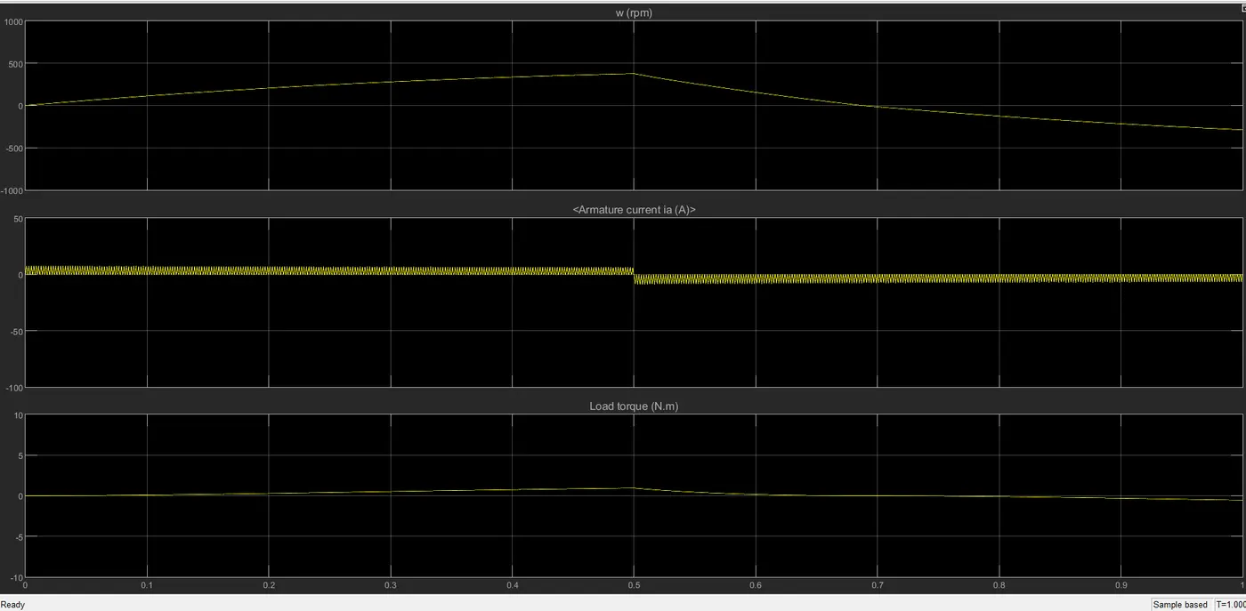
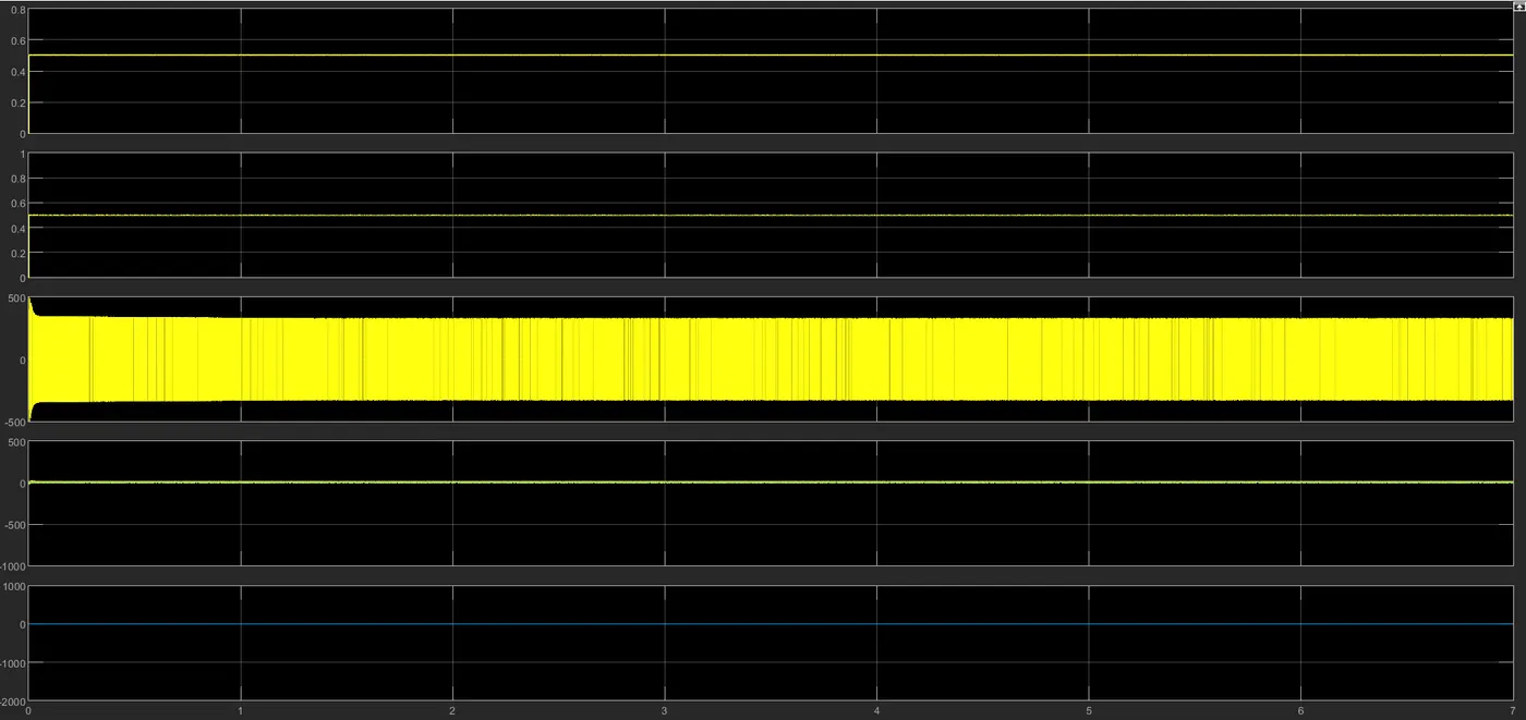
Based on the above results, it is clear that by keeping the duty cycle 45% there is no shoot up in armature current.
2. ‘The Four-Quadrant Chopper DC Drive (DC7) block’. Compare it with the H-bridge model.
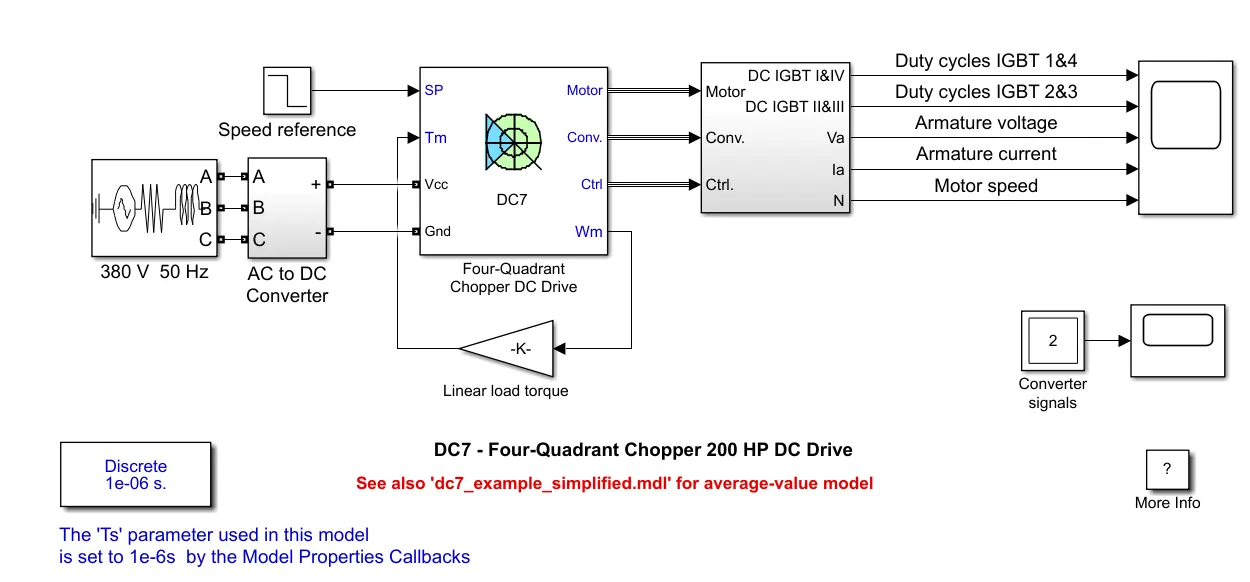
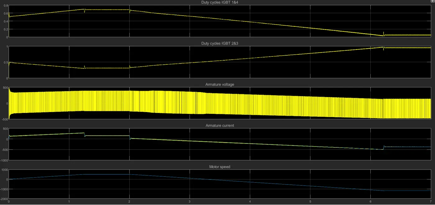
Comparison between H bridge model and four quadrent chopper is explained below,
| Four quadrent chopper | H Bridge |
|
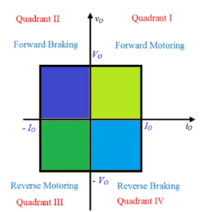
This can operate in 4 modes forward & reverse motoring, forward & reverse braking.
|
Forward and Reverse motoring are the only 2 operations. |
| Here the process is carried out based on the inputs recieved from the speed reference block. | Here the operations carried in the H-bridge depends upon the armature mean voltage through the pulse generator & Armature voltage control. |
| The maximum value of voltage can be achieved is 400V which on phase reversal becomes 200V. (Due to the presence of DC-AC converters, DC 7 model has the previleage to vary the magnitude of voltage at the desired level) | It consists of 4 IGBT diode pairs and the maximum voltage achieved is 300-350 V. |
| The Torque and output power bandwidth are broader. | Torque and output power are comparitvely narrower. (as it is restricted using single pulse generator) |
| Use of 4 quadrents in DC 7 model gives armature current more degrees of freedom. |
Range of armature current has lesser values comparitvely since only 2 pairs of IGBT & diode models are functioning at a time. |
3. Make a suitable EV model using the DC7 block and make a result report.
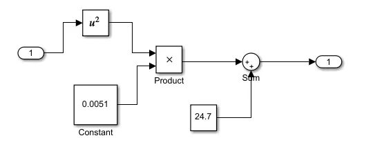
I have taken the previous sample block of the EV with DC 7 block and made the following changes, the speed reference was replaced with the "Driving block source". Also I changed the Linear load torque with the speed torque function T = 24.7 + 0.0051*(w^2)
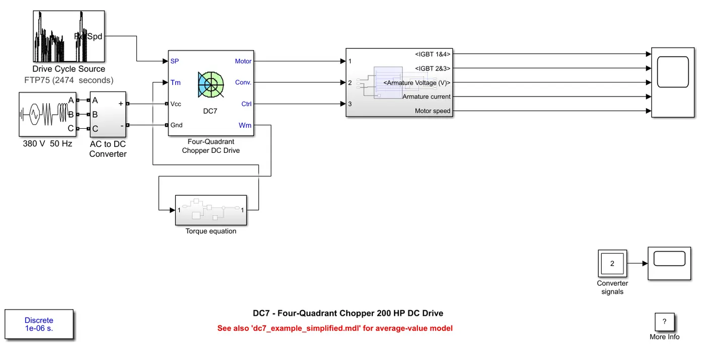
The subsystem block defining the Speed-Torque is shown below,
Conclusion: All questions were answered appropriately.