Week-7 Challenge: DC Motor Control
1. A. Explain a MATLAB demo model named ‘Speed control of a DC motor using BJT H-bridge’.
B. Comment on the armature current shoot-up from the scope results.
C. Refer to the help section of ‘The Four-Quadrant Chopper DC Drive (DC7) block’. Compare it with the H-bridge model.
Soln :
The bipolar junction transistor (BJT) when used for power switching applications, operates as an IGBT. When it is conducting (BJT operating in the saturated region), a forward voltage Vf is developed between collector and emitter (in the range of 1V). Therefore, the IGBT block can be used to model the BJT device. The IGBT block does not simulate the gate current controlling the BJT or IGBT. The switch is controlled by a simulink signal(1/0).
MOSFET(Metal Oxide Semiconductor Field Emission Transistor ):
MOSFET is used where frequency has to be maintained or high.Mosfet can handle high frequency of switching, we can see Mosfet in common in every circuit.Mosfet has three terminal they are Gate, discharge ,source.
IGBT(Insulated Gate Bipolar Transistor):
This is combination of BJT and Mosfet where it can work more load compared to both and it can work at high switching frequency condition, works same as BJT.
MATLAB demo model of 'Speed control of a DC motor using BJT H-bridge’ is as shown below:
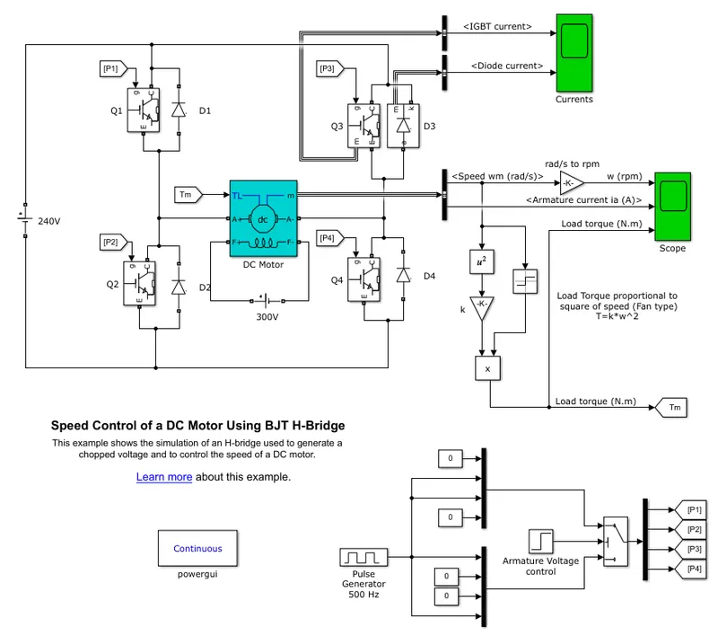
This model consists of a H-bridge with 4 BJT-Diode pair. The inputs such as duty cycle and step time are given from 'Pulse Generator block',Armature controlled voltage control block.
This H-bridge is made up of four switches Q1,Q2,Q3,Q4 and four diodes D1,D2,D3,D4. As IGBT can be used a switches when can be either in off or on position. When the motor is coasting it generates electricity due to the flexibility of this feature.
Different Modes Available :
- If Switch Q1 and Q4 is closed, this will cause the current to flow from the source, through switch 1 and then through the load, then through Switch Q4, then down to the ground. This is known as forward motion of the motor.
- If Switch Q2 and Q3 is closed, this will cause the current to flow from the source, through Switch 3 and then through the load, then through Switch 2, then down to the ground.This is known as Reverse motion of the motor.
- If Switch Q1,Q3 or Q2,Q4 is closed, then it will cause a short and burn out the H-bridge.
- If only one switch or none are closed, in this state the motor will be just coasting.
Working of Model :
- The DC motor uses the present model (5HP 24V 1750rpm). It simulates a fan type load. The armature mean voltage can be varied from 0 to 240V when the duty cycle (specified in the Pulse Generator block) is varied from 0 to 100%.
- The H-bridge consists of four BJT/Diode pairs (BJT simulated by IGBT models).
- Two transistors are switched simultaneously: Q1 and Q4 or Q2 and Q3. When Q1 and Q4 are fired, a positive voltage is applied to the motor and diodes D2-D3 operate as free wheeling diodes when Q1 and Q4 are switched off.
- When Q2 and Q3 are fired, a negative voltage is applied to the motor and diodes D1-D4 operate as free wheeling diodes when Q2 and Q3 are switched off.
- Q1 and Q4 act as Forward motoring.
- Q2 and Q3 act as Reverse motoring.
Simulation :
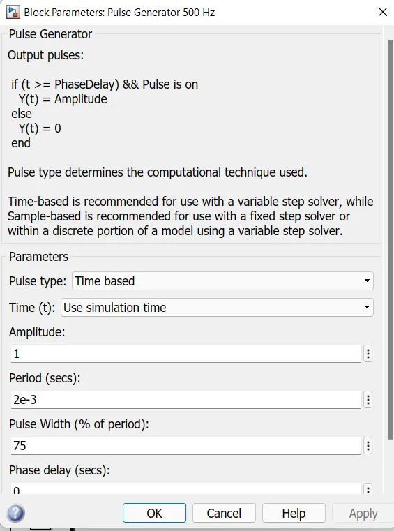
The motor starts in the positive direction with a duty cycle of 75% (mean DC voltage of 180V). At t=0.5 sec., the armature voltage is suddenly reversed and the motor runs in the negative direction.
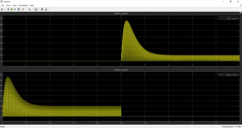
The above graphs shows the current passing through IGBT and Diode. So form 0 to 0.5 sec current is flowing through the diode D3 and 0.5 to 1 sec the current is passing through Q3.
Here Load torque is proportional to the square of angular velocity.
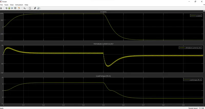
The above plot shows that at the begining of the cycle there is sudden peak in armature current, the same repeats in opposite direction when the motor rotates in opposite direction.
B. Comment on the armature current shoot-up from the scope results.
As the principle of pulse width modultation(PWM)
The average value of voltage (and current) fed to the load is controlled by turning the switch between supply and load on and off at a fast rate. The PWM switching frequency has to be high enough not perceived by the load must be as smooth as possible.
The armature current shoot-up is due to the sudden increase in voltage during the starting period. We have set of duty cycle to 75%.Means 75% of the 240V (180V) will be across the armature windings.
This can be easily changed by regulating the duty cycle i,e.. the peaks can be removed by reducing the duty cycle.
- By changing the duty cycle to 50% of the 240V(120V)
As there is a peak when the motor is switching directions ,Duty cycle is furture reduced to 40% and the following plot shows the output:
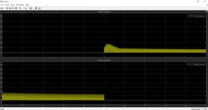
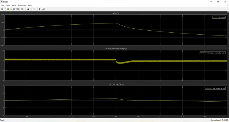
As the Duty cycle is reduced to 40% there is no sudden peak in the output.
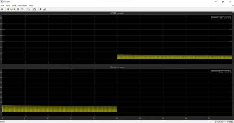
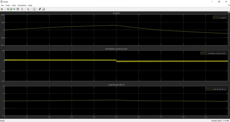
Conclusion : To reduce the shootup, we need to control the duty cycle gradually from 0-100%. This will in-effect gradually build the current flowing across the armature.
C. Refer to the help section of ‘The Four-Quadrant Chopper DC Drive (DC7) block’. Compare it with the H-bridge model.
Four Quadrant Chopper :
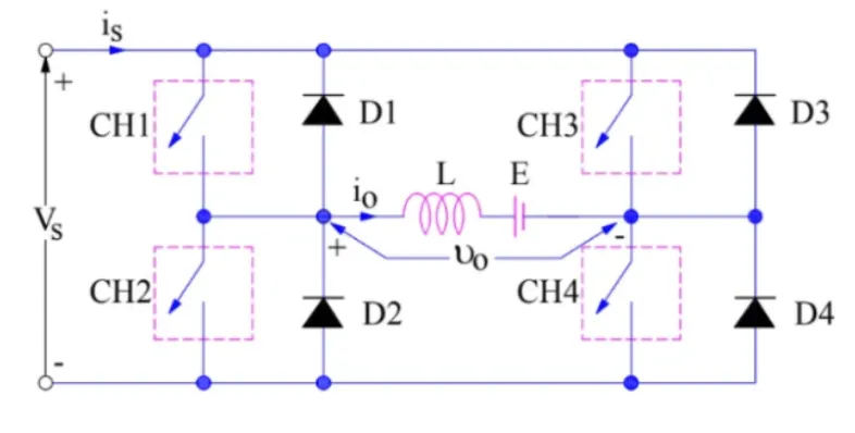
The Four Quadrants of operation:
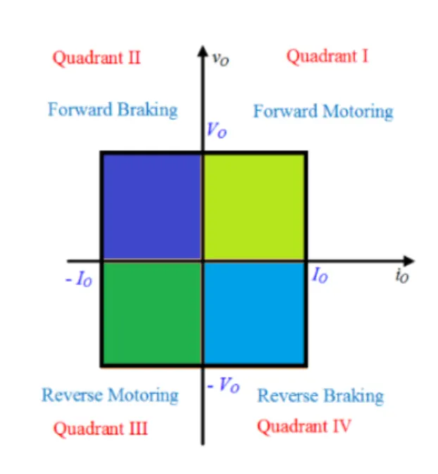
Operation of Quadrant1
Switch CH1 turned on :
As CH1 turned on, switches CH1 and CH4 conduct, output voltage Vo and the output current i, both are positives, power flows from source to load and inductor stores energy, the motor rotates in the forward direction hence called forward motoring.
Switch CH1 turned off :
Switch CH1 turned off but CH4 and diode D2 conducts, output current i, is positive and the output voltage vo becomes zero, inductor release energy, the motor rotates in the forward direction hence called forward motoring.
Quadrant2
Switch CH2 turned on :
Let us assume that the motor is running in the forward direction. Here switch CH2 operated, Switch CH3 and diode D4 conducts, output voltage v is zero and E, is responsible for the negative output current io. Machine behave as generator and inductor stores energy.
Switch CH2 turned off :
Here diode D4 and D1 conducts ,output voltagev, becomes positive and the ouput current i, is negative inductor release energy using diodes D4 and D1 power flows from load to source and hence called as forward braking. This is also known as regenerative braking.
Quadrant3
Switch CH3 turned on :
The polarity of back emf Eb must be reversed. Here switch CH3 operated, switches CH3 and CH2 conducts, output voltage vo and the output current i, both are negatives, power flows from source to load and inductor stores energy, the motor rotates in the reverse direction hence it is called as reverse motoring.
Switch CH3 turned off :
Switch CH3 turned off but switch CH2 and diode D4 conducts, ouput current i, is negative anf the output voltage v, becomes zero, inductor release energy and freewheeling action using diode D4 takes place, the motor rotates in the reverse direction, So the polarity of back emf is reversed, hence called as Reverse motoring.
Quadrant4
Switch CH4 turned on :
The polarity of back emf must be reversed.If that the motor is running in the reverse direction. Here switch Ch4 operated, switch CH4 and diode D2 conducts, output voltage vo is zero and E, is responsible for the positive output current io. Machine behave as generator and inductor stores energy.
Switch CH4 turned off :
The polarity of back emf must be reversed. Switch CH4 turned off, diode D2 and diode D3 conducts, output voltage vo becomes negative and output current i, is positive, inductor release energy using diodes D2 and D3. Power flows from load to source and hence called as reverse braking.
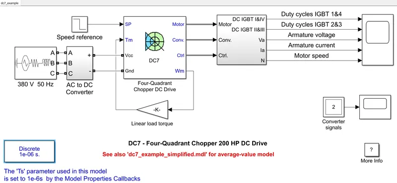
- The four-Quadrant Chopper DC Drive (DC7) block represents a four- quadrant, DC-supplied ,chopper(or DC-DC PWM converter) drive for DC motors.
- This drive features closed-loop speed control with four-quadrant operation. The speed control loop outputs the reference armature current of the machine.
- Using a PI current controller, the chopper duty cycle corresponding to the commanded armature current is derived.
- This duty cycle is then compared with a sawtooth carrier signal to obtain the required PWM signals for the chopper.
- The main advantage of this drive, compared with other DC drives, is that it can operate in all four quadrants(forward motoring, reverse regeneration, reverse motoring and forward regeneration).
- In addition, due to the use of high switching frequency DC-DC converters, a lower armature current ripple (compared with thyristor-based DC drives) is obtained. However, four switching devices are required, which increases the complexity of the drive system.
- The machine is separately excited with a constant DC field voltage source. There is thus no field voltage control. By default, the field current is set to its steady-state value when a simulation is started.
- The armature voltage is provided by an IGBT converter controlled by two PI regulators. The converter is fed by a constant DC voltage source. Armature current oscillations are reduced by a smoothing inductance connected in series with the armature circuit.
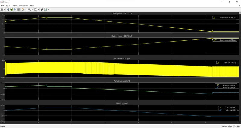
Simulation Output :
Comparing Four Quadrant Chopper and H-Bridge :
| Four Quadrant chopper characteristics: |
H-Bridge Characteristics: |
| Works in closed-loop system(feedback mechanism).The armature voltage is controlled by PI regulators. |
Works in Open Loop system (Non-feedback mechanism). |
| The motor is separately excited with a constant 150V DC field voltage source. |
The motor is not separately excited. |
| Regenerative braking is possible. | Regenerative braking is not possible but dynamic braking can be achived. |
| The current values are chopped not continous hence simulation takes less time. | The current values are continous. |
| Widely used in automobiles to control DC motor speed and direction. |
Widely used in robotics and electro-mechanical devices to control DC motor speed and direction. |
| To change to direction of motor current signals are interrupted with one another. | To change the direction of motor only the polarity of the current is changed. |
Q2. Develop a 2-quadrant chopper using simulink & explain the working of the same with the relevant results. (Refer to article - Multiquadrant operation of motor )
Soln:
Chopper :
A DC-to-DC converter, also known as DC chopper,is a static device which is used to obtain a variable DC voltage from a constant DC voltage source.
On this basis, there are two types of choppers: Step-up Chopper and Step-down Chopper.
A chopper whose average value of DC output voltage is more than the fixed DC input voltage is called Step-up Chopper.
A chopper whose average value of DC output voltage is less than the fixed DC input voltage is called Step-down Chopper.
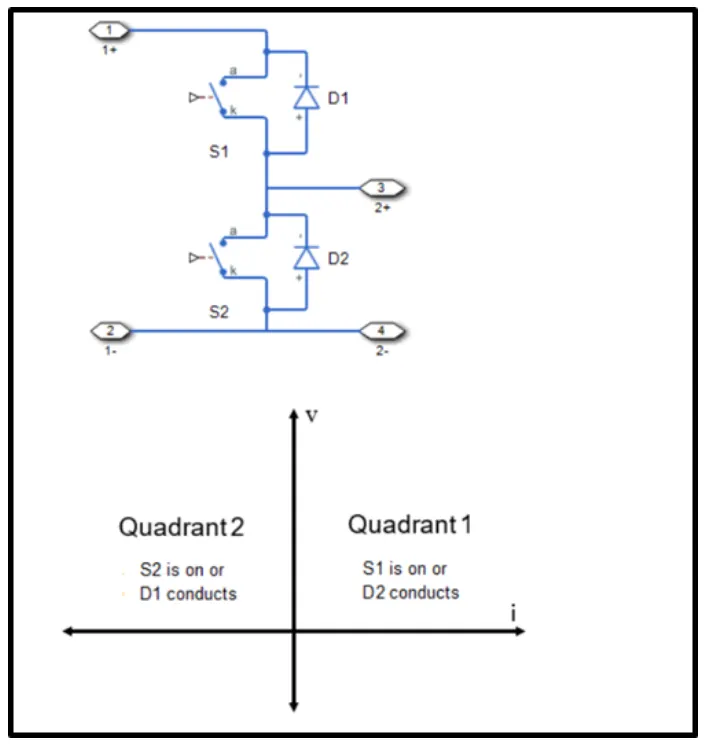
The Two-Quadrant Chopper block represents a two-quadrant controlled chopper for converting a fixed DC input to a variable DC output. The block contains two switching devices.
Two types of variants of Two-Quadrant Chopper :
Variant 1:
First and Second Quadrant Chopper Control :
Simulink Model:
This example shows how to control a two-quadrant chopper. The two-quadrant chopper operates in the first and second quadrants, allowing positive and negative output current.
The control subsystem implements a simple PI-based control algorithm for controlling the output curent.
The load of the the system is considered constant throughout the simulation.
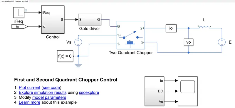 Switching Device :
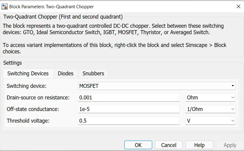 Simualtion Results:
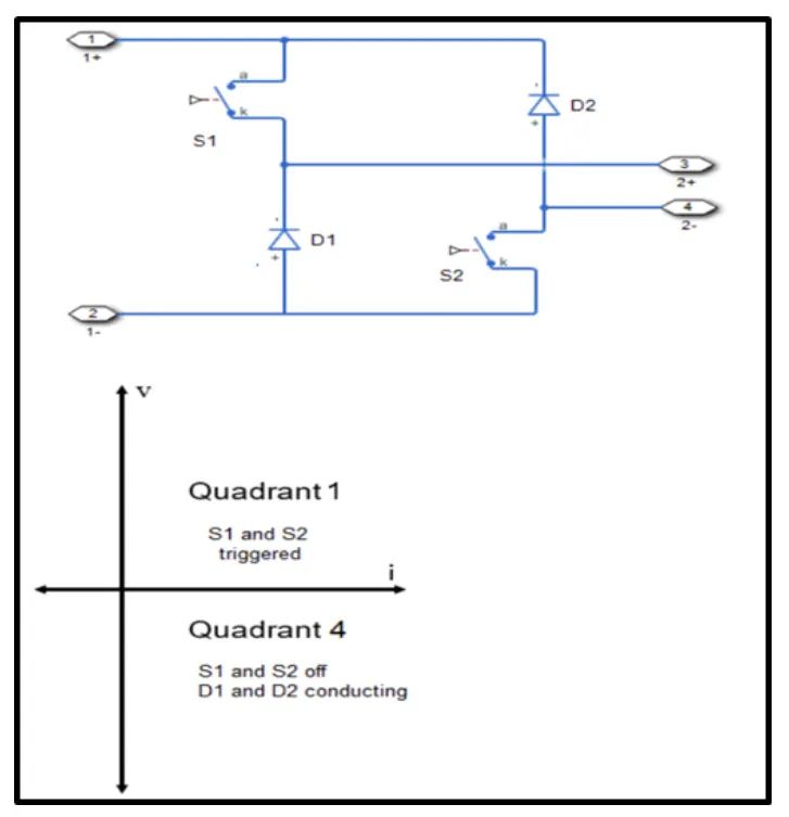
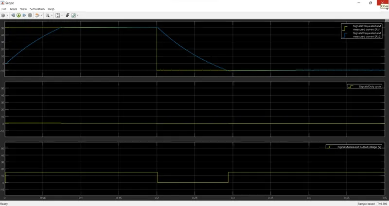 Variant 2: Quadrant 1-4 chopper control :
  Simulink Model :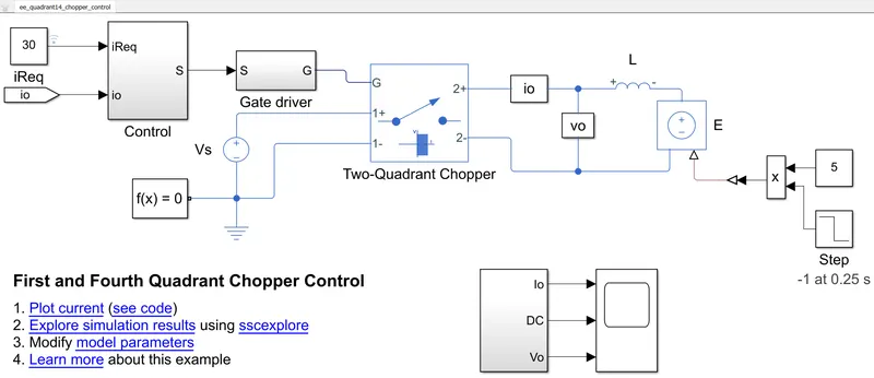
This example shows how to control a two-quadrant chopper. The two-quadrant chopper operates in the first and fourth quadrants, allowing positive and negative output voltage.
The control subsystem implements a simple PI-based control algorithm for controlling the output current.
The total simulation time(t) is 0.5 seconds. At t=0.25 seconds, the polarity of the load DC source E is changed.
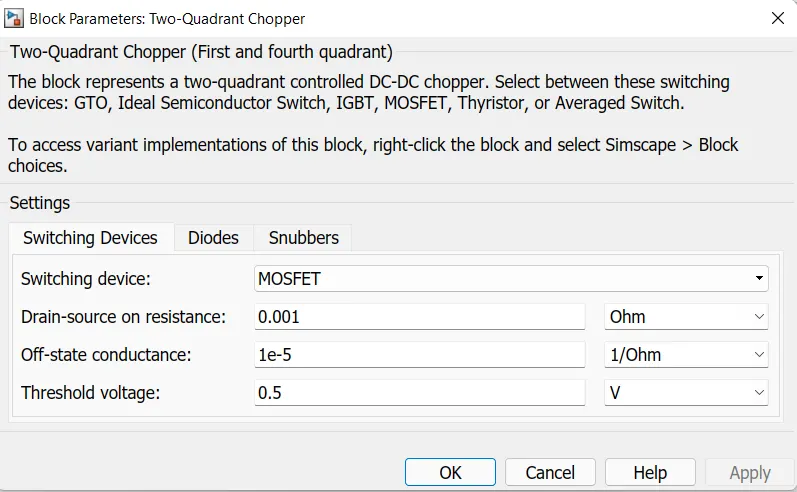
Switching Devices:
IGBT is used as switching device.
 Simulation Results: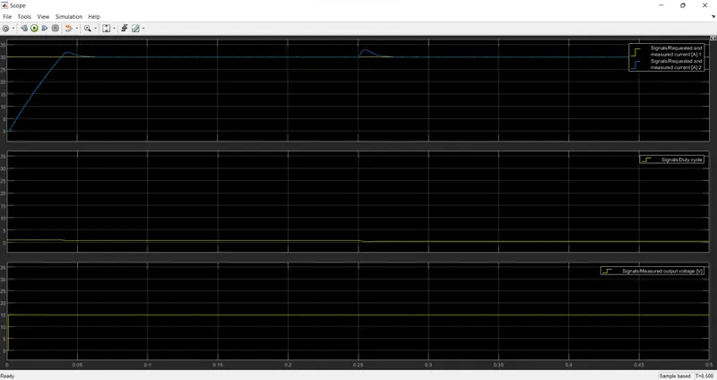
3. Explain in a brief about operation of BLDC motor.
Soln:
Brushless DC motors (BLDC)
- A motor converts supplied electrical energy into mechanical energy.
- Various types of motors are in common use.
- Among these, brushless DC motors (BLDC) feature high efficiency and excellent controllability, and are widely used in many applications.
- The BLDC motor has power saving advantages relative to other motor types.
Types of Motor :
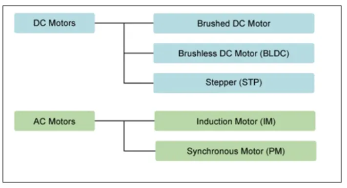
Machine ranging from simple devices like drills to complex equipment like industrial robots all make use of brushless DC motors that convert electrical energy into rotational motion.
Working principle of BLDC motor :
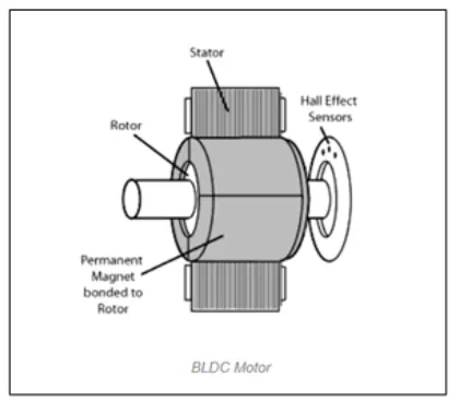
Both types of motors operate based on a similar principle, in which the rotational motion is generated through the attraction and repulsion of magnetic poles of permanent and electromagnets.
However, the way these motors are controlled is very different. BLDC's require a complex controller to convert a single DC power to three-phase voltage, whereas a brushed motor can be controlled by regulating the DC voltage.
As their name implies, brushless DC motors do not use brushes. With brushed motors,the brushes deliver current through the commutator into the coils on the rotor. Instead, the BLDC motor's rotor is a permanent magnet, the coils do not rotate, but are instead fixed in place on the stator. Because the coils do not move, there is no need for brushes and a commutator.
With the brushed motor, rotation is achieved by controlling the magnetic feilds generated by the coils on the rotor, while the magnetic field generated by the stationary magnets remains fixed. To change the rotation speed, you change the voltage for the coils. With a BLDC motor, it is the permanent magnet that rotates; rotation is achieved by changing the direction of the magnetic fields generated by the surrounding stationary coils. To control the rotion, you adjust the magnitude and direction of the current into these coils.
- The principles for the working od BLDC motors are the same as for a brushed DC motor, i.e, the internal shaft position feedback.
- In the case of a brushed DC motor, feedback is implemented using a mechanical commutor aand brushes.
- Within BLDC motor, it is achieved using multiple feedback sensors.
- In BLDC motors we mostly use a Hall-effect sensor, whenever rotor magnetic poles pass near the hall sensor, they generate a HIGH or LOW level signal, which can be used to determine the position of the shaft.
- If the direction of the magnetic field is reversed, the voltage developed will reverse too.
Advantages of BLDC motor:
- Better speed versus torque characteristics.
- High dynamic response
- High efficiency
- Long operating life due to lack of electrical and friction losses
- Noiseless operation
- Higher speed ranges
Applications of BLDC Motor:
The cost of the brushless DC motor has declined since its presentation, because of progressions in materials and design. This decrease in cost, coupled with the numerous focal points it has over the brush DC motor, makes the brushless DC motor a popular component in numerous distinctive applications. Applications that use the BLDC motor include, yet are not constrained to :
- Consumer electronics Controlling a BLDC motor:
- Transport
- Heating and ventilation
- Industrial engineering
- Model engineering
The control unit is implemented by microelectronics has several high-tech choices. This may be implemented using a micro-controller, a dedicated micro- controller, a hard-wired microelectronic unit, a PLC, or similar another unit.
The analog controller is still using, but the can not process feedback messages and control accordingl. With this type of control circuits, it is possible to implement high-performance control algorithms, such as vector control, field-oriented control, high-speed control all of which are related to electromagnetic state of the motor.
Speed control of the BLDC motor:
- Speed control of the BLDC motor is essential for making the motor work at the desired rate.
- The speed of a brushless DC motor can be controlled by controlling the input DC voltage.The higher the voltage, the more is the speed. When motor works in normal mode or runs below rated speed, the input voltage of armature is changed through the PWM model.
- When a motor is operated above rated speed, the flux is weakened by means of advancing the exiting current.
The speed control can be closed-loop or open-loop control.
Open Loop Speed Control - It involves simply controlling the DC voltage applied to motor terminals by choppingthe DC voltage. However this results is some form of current limiting.
Closed Loop Speed Control - It involves simply controlling the input supply voltage through the speed feedback from the motor. Thus the supply voltage is controlled depending on the error signal.
The closed-loop speed control consists of three basic components.
- A PWM circuit to generate the required PWM pulses. It can be either a microcontroller or a timer IC.
- A sensing device to sense the actual motor speed. It can be a hall effect sensor, an infrared sensor, or an optical encoder.
- A motor drive to control the motor operation.
Disadvantages of Brushless DC motors
- BLDC motor cost more than a brushed DC motor.
- The limited high power could be supplied to the BLDC motor, otherwise too much heat weakens the magnets and the insulation of winding may get damaged.