Week - 4
TASK : 1
Objective :
- Implement control logic of a “washing machine” using Stateflow as per given sequence:
- If the power supply is available, the system gets activated
- If the Water supply is not available, stop the process & indicate through LED
- Soaking time should be 200s followed by Washing time of 100s.
- Then rinsing happens for next 20s & dryer runs for 50s
Aim :
To implement control logic of a “washing machine” on simulink models using Stateflow.
Simulink Model :
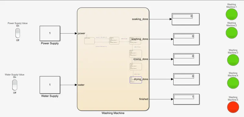
Washing Machine :
- We have chart block in the center within which we will define states and releated conditions.
- The inputs are given with constant block or any other block depending on the instance.Here we have power supply and water supply blocks as input to the chart block.
- Power supply block and water supply block are connected to Rocker switch to control logic of ON/OFF respectively.
- Output from the chart block are viewed from the display block ,depending on state transtions in chart block.
- When one state is completed ,we have a Lamp block to display that the state is completed or not.
- Within the chart block ,we have the different states with defined conditions. If the condition are satisfied ,the states are executed respectively.
- Once all the states are executed , the output are obtained .
State-flow Chart :
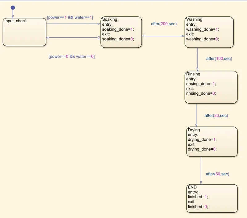
State-flow sequence for washing machine :
- If the power supply is available(1) ,the system gets activated.
- If the water supply is available process continue's ,else stop the process and indicate through lamp LED.
- Soaking time - 200 seconds.
- Washing time - 100 seconds.
- Rinsing time - 20 seconds.
- Drying time - 50 seconds.
- After all the processes have completed turn on the finished lamp LED.
Explanation :
- The power supply and water supply are given as input to the washing machine .
- In first state ,the inputs are checked. If there is no water supply or power supply ,further processes are not executed error is displayed.
- Then soaking process starts ,soaking is done for 200 seconds.
- After 200 seconds ,washing process starts ,washing is done for 100 seconds.
- After 300 seconds , rinsing process starts , rinsing is done for 20 seconds.
- After rinsing process ,drying process is done for 50 seconds.
- Finally after drying process all the processes is completed ,the washing machine is ended.
- This are indicated by the lamp LED when each of the processes is completed.
Output :
- When power supply is ON and Water Supply is OFF .
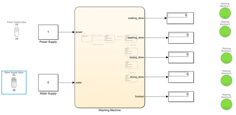
Result :
Washing Machine logic is built using state flow and given condition are executed respectively.
TASK : 2
Objective :
Make a Simulink chart for the “Gear shift” logic as per below conditions:
Speed Range(kmph) Gear
0 to 15 1
16 to 25 2
26 to 40 3
41 to 60 4
Above 61 5
Give speed input while the simulation is running & display the gear number.
AIM :
To implement simulink chart for the “Gear shift” on the given conditions.
Blocks Used :
1) Slider switch : This block toggles the value of the connected block parameter between two values during simulation.
2) Constant : constant value are added here.
3) Display : It is used display the final output of the function.
4) Stateflow-chart : It can be used as action language to implement control logic.
5) Lamp : Displays a color indicating the value of the input signal.
6) Slider Block : tunes the value of the connected block parameter during simulation.
7) Custom Gauge : Displays the value of the connected signal on a gauge face that you can customize to like a gauge in a real system.
Simulink Model :
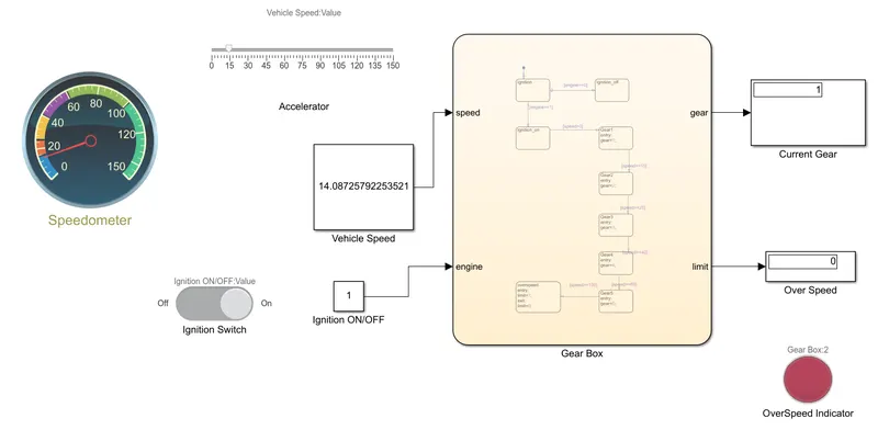
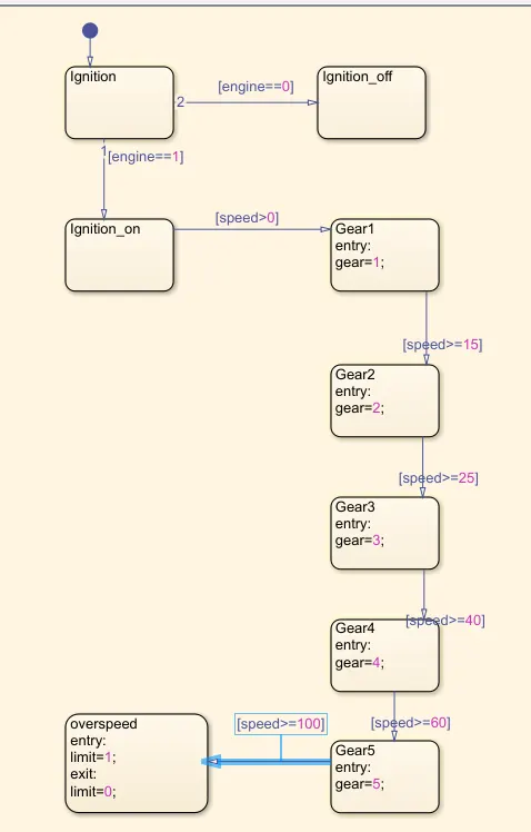
StateFlow-Chart :
Explanation :
- Assigning the parameters for the slider block is given below
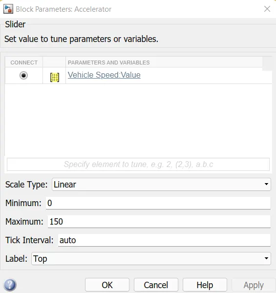
- The slider block is connected to a constant named "Vehicle Speed".
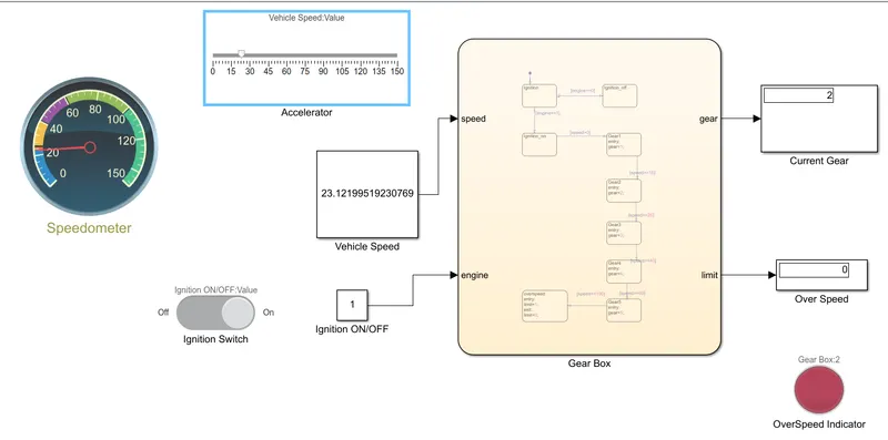
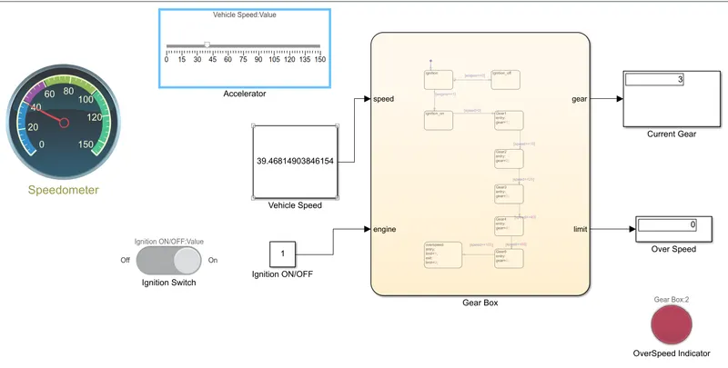
- The stateflow chart is having two inputs which are speed and engine.
- The speed input is connected with a constant named "Vehicle Speed" and engine input is connected with a constant block named "Ignition ON/OFF"
- The "Ignition ON/OFF" constant block is connected to slider switch block.
- In stateflow chart, checking ignition condition, we take "engine" as input giving the condition as "engine==0" ,this implies that vehicle is turned off .If condition is "engine==1", this implies that vehicle is turned on.
- After the ignition condition is turned on the state flows to the next processes. Speed conditions are defined for each block.
- When it exceeds the speed condition the process flows to the next block. All the conditions have been assigned to each block.
- The stateflow chart has two outputs namely "gear" and "limit" these outputs are connected to the display blocks.
- The "Current Gear"display block displays the exact gear at which the vehicle is running.
- The "Over Speed"display block displays the condition when the vehicle is attaining overspeed situation. Lamp is connected to the block to turn on when overspeed is reached.
Output :
When the speed is below 25km/hr :-
When the speed is below 40km/hr :-
When the speed is below 60km/hr :-
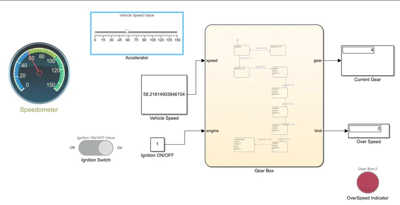
When the speed is above 60km/hr :-
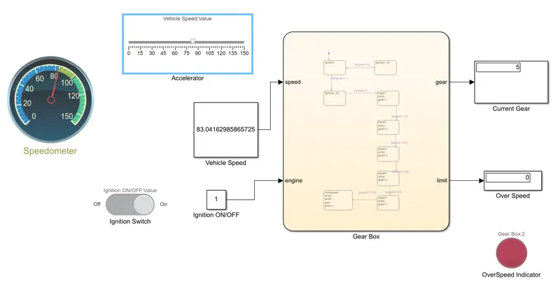
When the speed is above 100km/hr :-
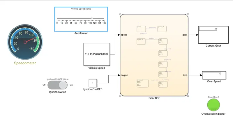
Result :
Simulation of gear shift corresponding to given speed range have been simulated sucessfully.