Week-6 Challenge: EV Drivetrain
1. Which types of power converter circuits are employed in electric and hybrid electric vehicle?
Soln :
power converter is an electrical or electro-mechanical device for converting electrical energy. A power converter can convert alternating current (AC) into direct current (DC) and vice versa; change the voltage or frequency of the current or do some combination of these.
power converters is to process and control the flow of electrical energy by supplying voltages and currents in a form that is optimally suited for user loads.
The power electronics converter can be classified into :
- Diode Rectifier
- AC to DC converter (Controlled Rectifier)
- DC to DC converter (DC chopper)
- AC to AC converter (AC voltage regulator)
- DC to AC converter (Inverter)
- Static Switches
AC to DC Converter (Controlled Rectifier) :-
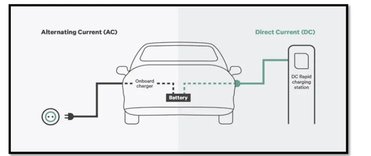
It is also called as "On board Charger" through it really is a converter. They are most commonly used in plug-in Hybird Electric Vehicles(PHEV) and plug-in Electric Vehicles(PEV). These vehicles get their propulsion power from an external electricity source (charging stations) which is alternating current. The battery needs to be charged using a direct current source.
DC-AC Converter (Inverter):-
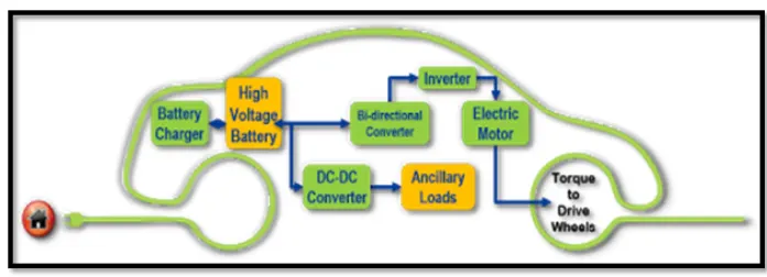
The DC/AC converter is required to convert the dc power to a suitable ac power for the electrical machine. The power output from battery pack(DC current) is converted using inverter to be used in electric motor(AC current).
DC-DC Converter (DC chopper) :-
DC-DC converters can be used to interface the elements in the electric power train by boosting or chopping the voltage levels.
By introducing DC/DC converters one can choose tthe voltage variation of the devices and the power of each device can be controlled. The power of the DC/DC converter depends on the characteristics of the vehicle such as top speed ,acceleration time from 0 to 100 km/h, weight, maiximum torque and power profile(peak power, continous power).
DC to DC converters are used to reduce High voltage DC input to low voltage DC output for some specific applicanes. They are also used to isolate some highly sensitive components in a circuit from other components of the circuit to avoid any kind of damage.
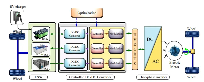
Electric vehicles (EV) use two different power systems; a high-voltage battery (200 to 450V DC) for traction and a low-voltage(12V) one for supplying all the electric appliances in the vehicle. Traditionally the low-voltage battery was charged from the alternator, but in today's vehicles it gets its power from the high-voltage battery pack. However, in specific electric car architectures, this low voltage battery should be ready to help recharge the high-voltage battery pack in order to provide energy for cranking the car. This means that the on-board DC-DC converter must be bi-directional and very efficient as well as highly reliable in order to run the complex control algorithms needed to ensure an energy-efficient solution.
EV Converter Types and Configurations
The complete classification of EV converters, including topology, control, modulation and optimization, is presented in below figure.
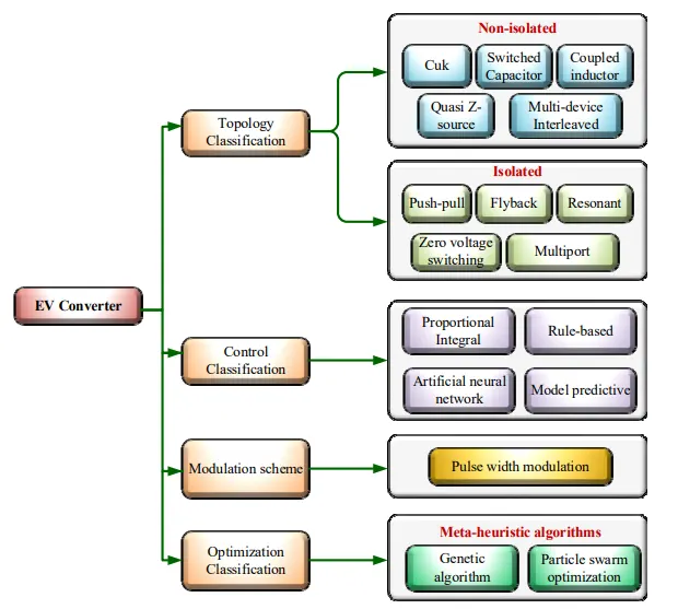
The configuration of converters in EVs can be categorized into two groups: non-isolated and isolated. The non-isolated converter is appropriate for EVs under medium- and high-power operation, while isolated DC-DC converters are suitable in EVs with low- and medium-power purposes.
2. An Electric Vehicle's powertrain with 72V battery pack in shown in the diagram below. The duty ratio for acceleration operation is 'd1' and for the braking operation the duty ratio is 'd2'.
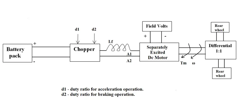
The other parameters of the electric vehicle is given below,
Motor and Controller Parameters:
Rated Armature voltage= 72 V
Rated armature current= 400 A
Ra= 0.5Ω, KΦ= 0.7 Volt second
Chopper Switching frequency= 400 Hz
The vehicle speed-torque characteristics are given by the below equation

What is EV steady state speed if duty cycle is 70%?
Soln :
Rated Armature voltage= 72 V
Rated armature current= 400 A
Armature Resistance(Ra) = 0.5Ω,
Motor Constant (KΦ) = 0.7 Volt second
Chopper Switching frequency= 400 Hz
Duty Cycle = 70% =0.70
WKT,
Vehicle Output Voltage(Vv) is given by :-
Vv = Battery Voltage (V) * Duty cycle
Vv = 72 * 0.70
Thus , Vehicle Voltage = 50.4V
Now ,equation for vehicle is given by :-
Tv = ((Vv - ω.Kϕ) .Kϕ) / Ra
Where,
Tv = vehicle Torque(N-m)
Vv = vehicle voltage(volts)
ω = steady state speed of vehicle(rps)
By substituting all these values in equation, we get :
Tv = ((50.4 - 0.7ω).0.7)/0.5
= 70.56 - 0.98ω .........eq(1)
.... eq(2)
Solving equations(1) &(2)
comparing both torque of vehicle and torque of motor,
24.7 + (0.0051).ω2 = 70.56 - 0.98ω
0.0051ω2 + 0.98ω - 45.86 = 0
By solving this by quadratic equation we get,
we get two ω values as
ω = 38.85 rad/sec and ω = -230.95 rad/sec
we take the positive value ,
Therefore Steady state speed of vehicle = 38.85 rad/sec or 371rpm
Q3. Develop a mathematical model of a DC Motor for the below equation using Simulink.
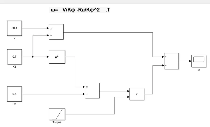
ω= V/Kϕ - Ra/Kϕ^2 .T
Soln :
DC motor : An electric motor is an electrical machine that converts electrical energy into mechanical energy. Most electric motors operate through the interaction between the motor's magnetic field and electric current in a wire winding to generate force in the form of torque applied on the motor's shaft. An electric generator is mechanically identical to an electric motor, but operates with a reversed flow of power, converting mechanical energy into electrical energy.
ω = V/Kϕ - Ra/Kϕ^2 .T
V = Vehicle Voltage
Ra = Armature Resistance
Kϕ = Motor constant
T = Torque
By taking the previous question2 values as input to the blocks we have constructed below mathematical model for the given equation.
mathematical model :
Result :
We have given run time as 100sec ,then they model is run, we obtained result as shown below.
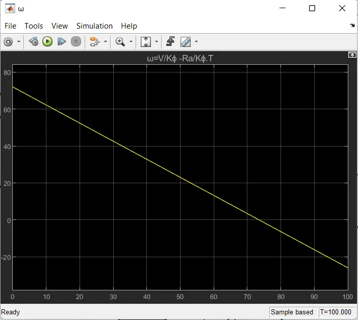
Above figure is the speed torque characteristics of dc motor, it shows starting torque is about 71Nm, torque becomes zero when speed is 70.5
Q4. Refer to the blog on below topic:
Induction Versus DC brushless motors by Wally Rippel, Tesla
Explain in brief about author’s perspective
Soln:
Wally rippel first explains working of brushless DC motor and AC induction motor.
Brushless DC motor, the rotor includes two or more permanent magnets that generate a DC magnetic field(as seen from the vantage point of the rotor). In turn, this magnetic field enters stator core(a core made up of thin, stacked laminations) and interacts with currents flowing within the windings produce a torque interaction between the rotor and stator. As the rotor rotates ,it is neccessary that the magnitude and polarity of the stator currents be continously varied and in just the right way - Such that the torque remains constant and the conversion of electrical to mechanical energy is optimally efficient. The device that provides this current control is called an inverter. Without it, brushless motors are useless motors.
Induction motors has stator winding, but its rotor does not have permanent magnets like DC motors, rotors contain laminated steels stacks ,its a self starting motor ,doesnot require inverter for starting, In contrast a brushless DC motor produces no starting torque when directly connected to fixed frequency utility power they have limited starting torque and somewhat limited running peak torque capabilities, when compared to DC type machines. DC brushless drivers require only a speed sensor; these differences are relatively small. Brushless drive, the strength of the magnetic field produced by the permanent magnets would be adjustable. When maximum torque is required, especially at low speeds, the magnetic field strength(B) should be maximum - So that inverter and motor currents are maintained at their lowest possible values. This minimizes the I^2R losses and thereby optimizes efficiency. Likewise ,when torque level are low, the B field should be reduced such that eddy and hysteresis losses due to B are also reduced. Ideally, B should be adjusted such that the sum of the eddy, hysteresis and I^2 losses is minimized. Unfortunately, there is no easy wat of changing B with permanent magnets. In contrast, induction machines have no magnets and B fields are "adjustable', since B is proportionate to V/f. With DC brushless, as machine size grows, losses do not necessarily grow.
His conclusion is that DC brushless drives will likely continue to dominate in the hybird and coming plug-in hybird markets, and that induction drives will likely maintain dominance for the high-performance pure electrics. The hardware is common for both drives could mean that wwe will see induction and DC brushless live and work side by side during the coming golden era of hybird and electric vehicles.
| BLDC Motor |
AC Induction Motor |
| The speed/Torque characteristics is flat in nature. | The speed/Torque characteristics is non-linear in nature. |
| It enables operations at all speeds with rated load. | It enables lower torque at lower speeds. |
| Output power/frame size is high ,because it has permanent magnets on the rotor, the smaller size can be achived for a ggiven output power. | Output power/frame size is moderate,because both stator and rotor have winding, output power to size is lower than BLDC. |
|
The rotor inertia is low. This enables better dynamic characteristics. |
The rotor inertia is high. This enables poorer dynamic characteristics. |
| The starting current is rated. No special srarter is required. | The starting current is approximately up to 7 times of rated. Stator circuit rating should be carefully selected. It normally uses a star delta starter. |
| A controller always required to keep the motor running. | No controller is required for fixed speed. |
| The controller can be used for variables speed control. | A controller is required only if variable speed is desired. |
| No slip is experienced between stator and rotor frequencies. | The rotor runs at a lower frquency than the stator by slip frequency and slip increases with no loaf on the motor. |