Week -2
Task : 1
Objective :
Make a Simulink model of Doorbell using solenoid block with the following details:
In the above arrangement, when the switch is closed the electromagnet receives electrical power from the battery and pulls the metal arm to hit the bell producing sound.
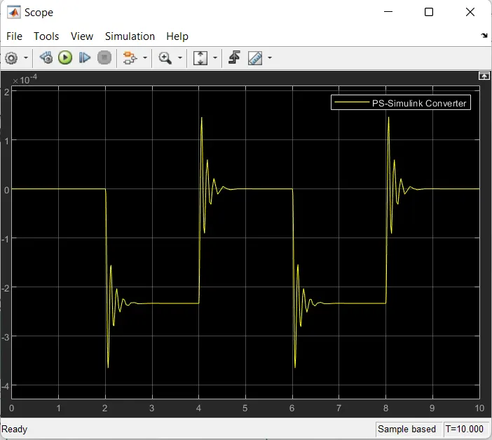
Create a situation where the switch is closed for 2 seconds and then released. Observe the physical movement of the plunger.
Aim :
Make a Simulink model of Doorbell using solenoid block and Create a situation where the switch is closed for 2 seconds and then released.
Model :
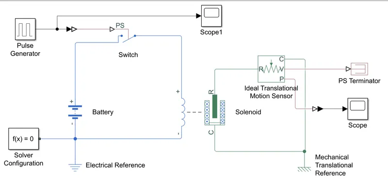
Explanation :
- PulseGenerator
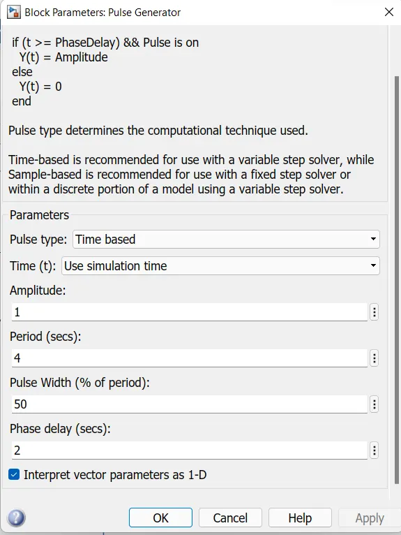
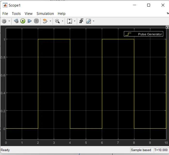
- A pulse generator is given as input with following specifications .
- The condition was that the bell is engaged(closed) for 2 seconds and then released.
- Same is implemented by giving period as 4 seconds and pulse width as 50% of 4 seconds ,i.e, 2 seconds.Phase delay is given as 2 seconds ,so the simulation starts from unengaged(released) condition of switch.
- The signal from pulse generator is converted with simulink-PS converter and given as input to the switch.
- The switch block is controlled by external physical signal ,if the external signal is greater than threshold parameter then the switch is closed ,otherwise switch is open.
- A solenoid block is introduced and battery(12V) is connected to it.
- Positive terminal of battery is connected to switch and then connected to positive terminal of the solenoid block.
- Negative terminal of battery is connected to the negative terminal of the solenoid block ,with electrical reference block and solver configuration to complete the electric circuit.
- Port R from solenoid block is connected to R terminal of Ideal translational motion sensor.
- Ideal translational motion sensor is used to observe the movement of the plunger.
- Port C from solenoid block and C terminal of Ideal translational motion sensor is connected to mechanical reference block to complete the mechanical block.
- V terminal of Ideal translational motion sensor is terminated using PS Terminator.
- P terminal of Ideal translational motion sensor is connected to scope to view the output plot.
Output :
Result :
Simulink model of Doorbell using solenoid block is built and switch is closed for 2 seconds and then released for every 2 seconds.
Task : 2
Objective :
Use a thermistor to sense the temperature of a heater & turn on or turn off the fan as per the below conditions:
Temperature source: 20 °C from 0 to 10 seconds, 27 °C from 10 to 30 seconds, 23 °C from 30 to 50 seconds
Fan conditions: ON if the temperature above 25 °C, OFF otherwise
Aim :
To create a simulink model of thermistor to sense the temperature of a heater and turn on or off the fan.
Blocks used :
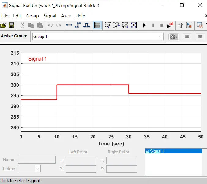
1) Signal Builder(Input) : Its used to give the input as per the given conditions
.
Inputs :
At point1 - Time 0 seconds - Temperature - 293K,
At point2 - Time 10 seconds - Temperature - 293K,
At point3 - Time 10 seconds - Temperature - 300K,
At poin4 - Time 30 seconds - Temperature - 300K,
At point5 - Time 30 seconds - Temperature - 296K,
At point6 - Time 50 seconds - Temperature - 296K,
2) Controlled Temperature Source : It represents an ideal source of thermal energy that is powerful enough to maintain specified temperature difference across the source regardless of the heat flow consumed by the system.
3) Thermistor : It is type of resistor whose resistance is dependent on temperature, more so than in standard resistors.
The Thermistor block represents an NTC thermistor using the B-parameter equation.
NTC - Neagtive Temperature Co-efficient
4) Resistor : The resistor block models a linear resistor, with equation: V=I.R
where V-Voltage,I- Current, R- Resistance
5) Voltage Sensor : This block represents an ideal voltage sensor, its a device that converts voltage measured between two points of an electrical circuit into a physical signa; proportional to the voltage.
Explanation :
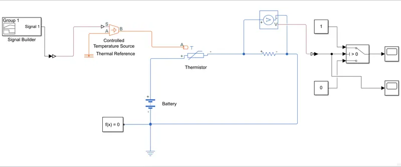
- Inputs from signal builder is given to port S of Controlled Tempertaure Source, port A is connected to thermal reference and then port B connected to the port A of thermistor.
- Thermistor's positive terminal is connected to battery supply(12V).
- Thermistor is connected with Resistor ,ensure that thermistor connected with positive terminal of the resistor and voltage across the resistor is given by V(+)_V(-).
- This convention ensures that the power absorbed by a resistor is always positive.
- Now connect the Voltage Sensor in a series connection to the resistor ,ie.,positive terminal towards thermistor and negative terminal to negative terminal of the battery.
- Output terminal of the voltage Sensor is connected to Switch.
- Switch parameter for giving the giving condition as Fan must be ON if the temperature above 25°C, OFF otherwise.
- Output is Sucessfully executed by connecting with scope as per the given condition.
Output :
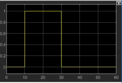
- For 0-10 seconds fan is in OFF condition, because temperature is 293K which is below 298K.
- After 10 seconds temperature goes to 300K, so Fan will turn ON.
- After 30 seconds fan will turn OFF because temperature goes back to 296k which is below 298K.
Result :
Fan is turned OFF/ON sucessfully ,depending on the given input temperature.