Week-7 Challenge: DC Motor Control
Problem 01:
A.
Aim:
To explain a MATLAB demo model named ‘Speed control of a DC motor using BJT H-bridge’.
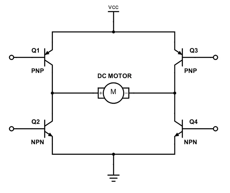
An H-bridge is a simple circuit that lets you control a DC motor to go backward or forward. You normally use it with a microcontroller, such as an Arduino, to control motors. An H-bridge is built of four switches that control the flow of current to a load. In the image above, the load is the M connecting the two sets of switches. Using one current source, you can drive the current in two directions by closing two switches.
The circuitry behind a simple H-Bridge:
If Switch 1 and 4 are closed, then the current will flow from the left to right:
Simulink Model:
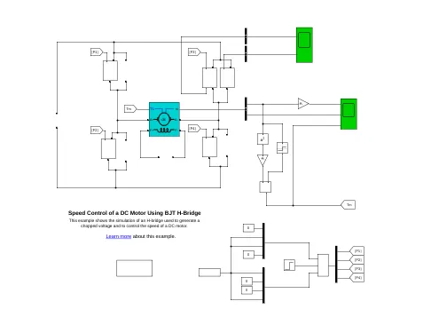
The Bipolar Junction Transistor (BJT) when used for power switching applications, operates as an IGBT. When it is conducting (BJT operating in the saturated region), a forward voltage Vf is developed between collector and emitter (in the range of 1 V). Therefore, the IGBT block can be used to model the BJT device.
The IGBT block does not simulate the gate current controlling the BJT or IGBT. The switch is controlled by a Simulink® signal (1/0). The DC motor uses the preset model (5 HP 24V 1750 rpm). It simulates a fan type load (where Load torque is proportional to square of speed). The armature mean voltage can be varied from 0 to 240 V when the duty cycle (specified in the Pulse Generator block) is varied from 0 to 100%.
The H-bridge consists of four BJT/Diode pairs (BJT simulated by IGBT models). Two transistors are switched simultaneously: Q1 and Q4 or Q2 and Q3. When Q1 and Q4 are fired, a positive voltage is applied to the motor and diodes D2-D3 operate as free-wheeling diodes when Q1 and Q4 are switched off. When Q2 and Q3 are fired, a negative voltage is applied to the motor and diodes D1-D4 operate as free-wheeling diodes when Q2 and Q3 are switched off.
Simulation:
- The motor starts in the positive direction with a duty cycle of 75% (mean DC voltage of 180V). At t= 0.5 sec., the armature voltage is suddenly reversed and the motor runs in the negative direction.
- 'Scope' shows motor speed, armature current and load torque and 'Currents' shows currents flowing in BJT Q3 and diode D3.
Current Output:
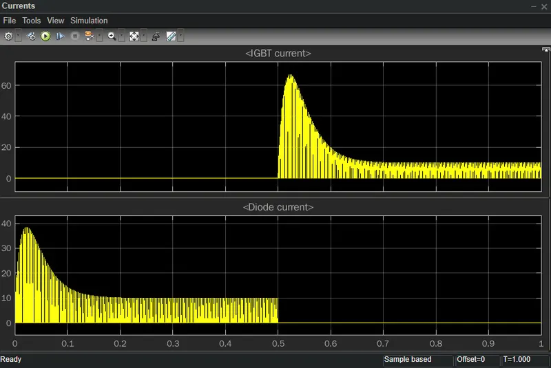
At the duty cycle of 75% the motor gets started. The Current flows through diode, when the current increases from 0.5 seconds and decreases on 1 sec.
Speed Output:
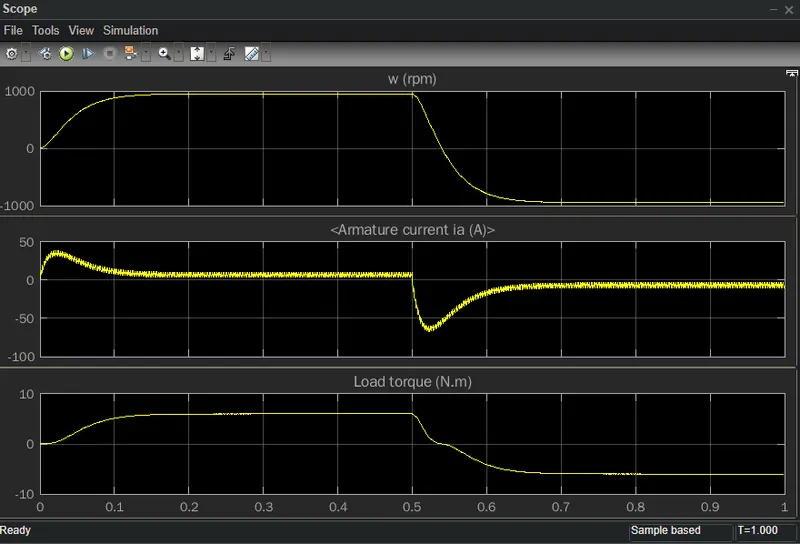
The sudden spike happens current at 0.5 sec and also the current goes negative half cycle.
1B.
Aim:
To comment on the armature current shoot-up from the scope results.
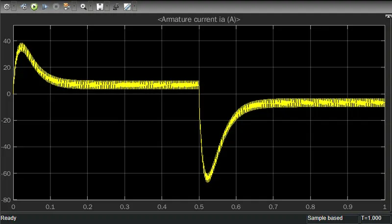
Due to the sudden change in the initial current, the motor runs in the 75% duty cycle.
By Changing the duty cycle 75% to 50%.
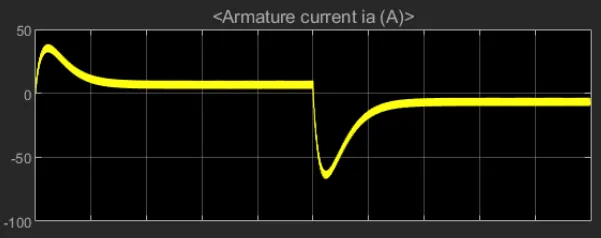
When reducing the duty cycle the current shoot up is reduced gradually.
1C.
Aim:
To compare the H-Bridge Model with the Four-Quadrant Chopper DC Drive (DC7) block.
The Four-Quadrant Chopper DC Drive (DC7) block represents a four-quadrant, DC-supplied, chopper (or DC-DC PWM converter) drive for DC motors. This drive features closed-loop speed control with the four-quadrant operation. The speed control loop outputs the reference armature current of the machine. Using a PI current controller, the chopper duty cycle corresponding to the commanded armature current is derived. This duty cycle is then compared with a sawtooth carrier signal to obtain the required PWM signals for the chopper.
First quadrant Operation:
For first quadrant operation, CH4 is kept ON, CH3 is kept OFF and CH1 is operated. When both CH1 & CH4 are ON simultaneously, the load gets directly connected to the source and hence the output voltage becomes equal to the source voltage. This essentially means that vo = vs. It may be noted that the load current flows from source to load as shown by the direction of io. When CH1 is switched OFF, the load current free wheels through CH4 and D2. During this period, the load voltage and current remains positive.
Second Quadrant Operation:
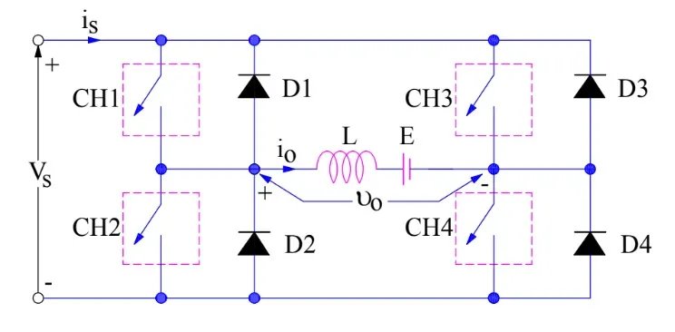
To obtain second quadrant operation, CH2 is operated while keeping the CH1, CH3 & CH4 OFF. When CH2 is ON, the DC source in the load drives current through CH2, D4, E and L. Inductor L stores energy during the On period of CH2. When CH2 is turned OFF, current is fed back to the source through D1, D4. It should be noted at this point that (E+Ldi/dt) is more than the source voltage Vs. As load voltage Vo is positive and Io is negative, it is second quadrant operation of chopper. Since, the current is fed back to the source, this simply means that load is transferring power to the source.
Third Quadrant Operation:
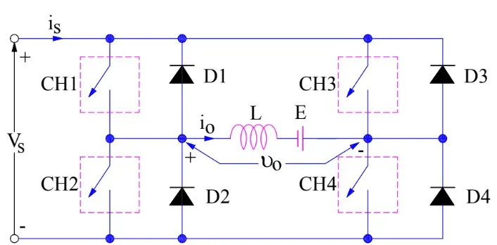
To obtain third quadrant operation, both the load voltage and load current should be negative. The current and voltage are assumed positive if their direction matches what shown in the circuit diagram. If the direction is opposite to what shown in the circuit diagram, it is considered negative. One important thing to notice is that the polarity of emf E in load must be reversed to have a third quadrant operation.
Fourth Quadrant Operation:
- To obtain the fourth quadrant operation, CH4 is operated while keeping CH1, CH2, and CH3 OFF. The polarity of load emf E needs to be reversed in this case too like the third quadrant operation.
- When CH4 is turned ON, positive current flows through CH4, D2, L, and E.
- Inductance L stores energy during the time CH4 is ON. When CH4 is made OFF, the current is fed back to the source through diodes D2 and D3.
- Here load voltage is negative but the load current is always positive. This leads to chopper operation in the fourth quadrant.
- Here, power is fed back to the source from the load, and the chopper acts as a step-up chopper.
Problem 03:
Aim:
To develop a 2-quadrant chopper using Simulink & explain the working of the same with the relevant results.
First and second quadrant.
The Two-Quadrant Chopper block represents a two-quadrant controlled chopper for converting a fixed DC input to a variable DC output. The block contains two switching devices. Options for the type of switching devices.
First and fourth quadrant.
The block contains an integral protection diode for each switching device. The integral diode protects the semiconductor device by providing a conduction path for reverse current. An inductive load can produce a high reverse-voltage spike when the semiconductor device suddenly switches off the voltage supply to the load.
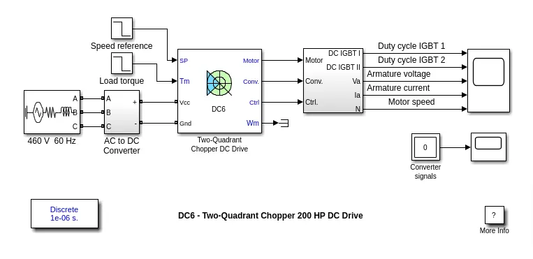
Simulation Results:
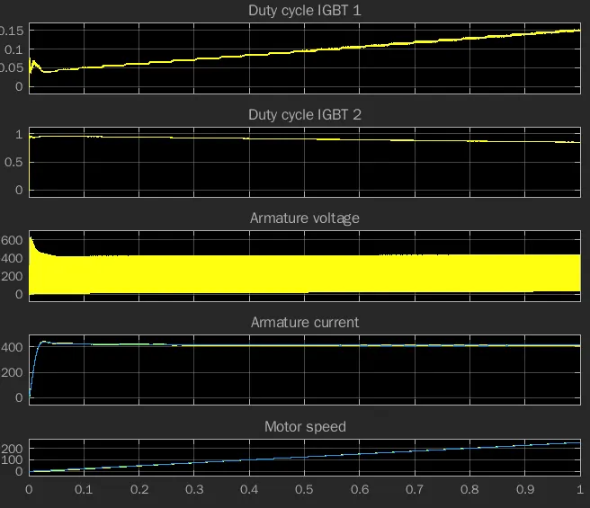
The armature current and motor speed increases gradually. The duty cycle 1 and 2 is reducing and suddenly increased duty cycle.
Problem 03:
Aim:
To give breif note on operation of BLDC motor.
BLDC motor:
A Brushless DC Electric Motor (BLDC) is an electric motor powered by a direct current voltage supply and commutated electronically instead of by brushes like in conventional DC motors. BLDC motors are more popular than the conventional DC motors nowadays, but the development of these type of motors has only been possible since the 1960s when semiconductor electronics were developed. When engineers are faced with the challenge of designing electrical equipment to perform mechanical tasks, they might think about how electrical signals get converted to energy. So actuators and motors are among the devices that convert electrical signals into motion. Motors exchange electrical energy to mechanical energy.
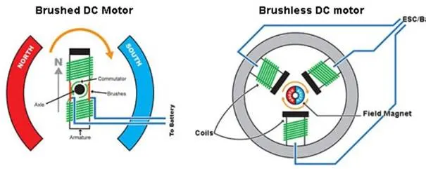
Operations of BLDC Motors:
Brushless DC motors do not use brushes. With brushed motors, the brushes deliver current through the commutator into the coils on the rotor. So how does a brushless motor pass current to the rotor coils? It doesn’t—because the coils are not located on the rotor. Instead, the rotor is a permanent magnet; the coils do not rotate, but are instead fixed in place on the stator. Because the coils do not move, there is no need for brushes and a commutator.
Advantages of BLDC Motors:
- A BLDC motor with three coils on the stator will have six electrical wires (two to each coil) extending from these coils.
- In most implementations three of these wires will be connected internally, with the three remaining wires extending from the motor body (in contrast to the two wires extending from the brushed motor described earlier).
- Wiring in the BLDC motor case is more complicated than simply connecting the power cell’s positive and negative terminals; we will look more closely at how these motors work in the second session of this series. Below, we conclude by looking at the advantages of by BLDC motors.
- One big advantage is efficiency, as these motors can control continuously at maximum rotational force (torque).
- Brushed motors, in contrast, reach maximum torque at only certain points in the rotation. For a brushed motor to deliver the same torque as a brushless model, it would need to use larger magnets. This is why even small BLDC motors can deliver considerable power.
Ideal Applications of BLDC Motors:
- They have long been used in washing machines, air conditioners, and other consumer electronics; and more recently, they are appearing in fans, where their high efficiency has contributed to a significant reduction in power consumption.
- They are also being used to drive vacuum machines. In one case, a change in the control program resulted in a large jump in rotational speed—an example of the superlative controllability offered by these motors.
- BLDC motors are also being used to spin hard disc drives, where their durability keeps the drives operating dependably over the long term, while their power efficiency contributes to energy reduction in an area where this is becoming increasingly important.