Project
Aim:
To prepare a technical report explaining the model properties and comments on the results.
Objective:
To carry out a system-level simulation of an all-terrain vehicle(BAJA ATV) and prepare a technical report explaining the model properties and comments on the results.
Explanation: All-Terrain Vehicle
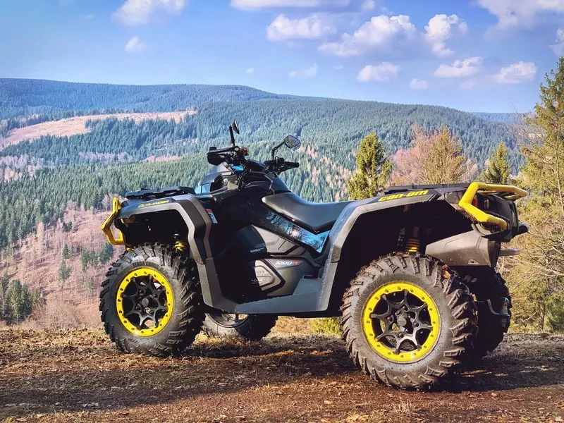
An all-terrain vehicle (ATV) is defined as a motorized off-highway vehicle designed to travel on four low-pressure or non-pneumatic tires, having a seat designed to be straddled by the operator and handlebars for steering control. This vehicle runs on low-pressure tires. However, it has handlebars instead of wheel for controlling the steering. As the name indicates, an ATV is designed to handle a broader variety of terrain than regular vehicles.
Working:
- ATV engines work by pulling oxygen and fuel into the combustion chamber, allowing the piston to push upward and combust the mixture.
- There's a controlled explosion that propels the vehicle forward or backward, releasing exhaust through the outlet.
- ATVs come with two-stroke and four-stroke engines.
Model 01:
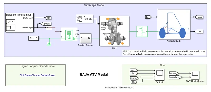
Simulink Model of BAJA ATV with CVT:
Blocks Used:
CVT - Continuous Vehicle Transmission
In a Continuous Vehicle Transmission, the push belt transfers the torque from one pulley to other. The level of power transmission is adopted automatically through continuous variable adjustment of the pulleys. Unlike a conventional automatic transmission system, the CVT does not make use of gears. Instead, it has two pulleys, whose diameters are variable and are connected by a belt or a chain. One end is connected to the engine and the other one is linked to the wheels, where the power is delivered. The pulleys are movable and as they come closer to each other, the belt or the chain rides higher making the diameters of the pulleys larger and vice-versa.
CVT Block:
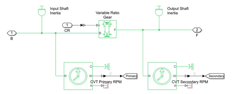
Variable Gear Ratio - This block is like a gearbox for the CVT system and it is implemented by a mechanical belt. It has input 'r' refines the ratio of input to output angular shaft velocities. Port B and F are mechanical rotational ports.
Vehicle Body:
Other Blocks Used:
Generic Engine - This block represents a system-level model of spark ignition and diesel engines. It has a Throttle 'T' and brake 'B' as input. The terminal of F and B are Mechanical reference ports, whereas, P and FC are Physical signal output ports.
Signal Builder - The Signal Builder block is used to set brake and throttle as input signals to the engine.
CVT Model Output 1:
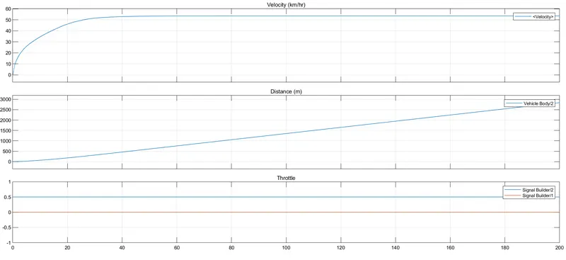
From the above graph, the throttle input is 0.5 given by the signal builder and also brake is 0. As the brake zero, then the velocity of the vehicle gradually increased from 0 to 55 kmph, and then it is constant. while velocity increases the distance traveled by the vehicle should increases.
CVT Model Shaft Output:
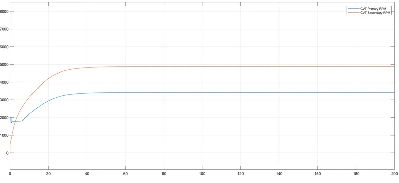
From the above shaft speed output, the values differ with respect to the gear ratio. It shows the variation of angular velocities of input and output shafts.
Model 02:
Simulink Model of BAJA ATV with CVT using Dashboard:
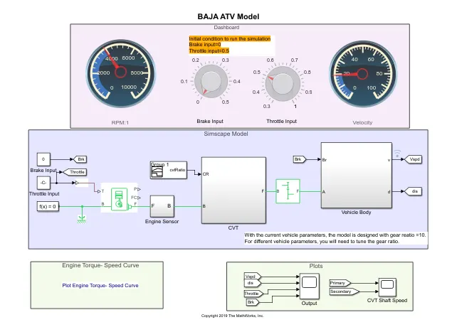
This is also a CVT model but here the throttle and brake are adjusted using a knob that is a dashboard. By using this we can vary the input while the simulation is running.
Model 2 output:
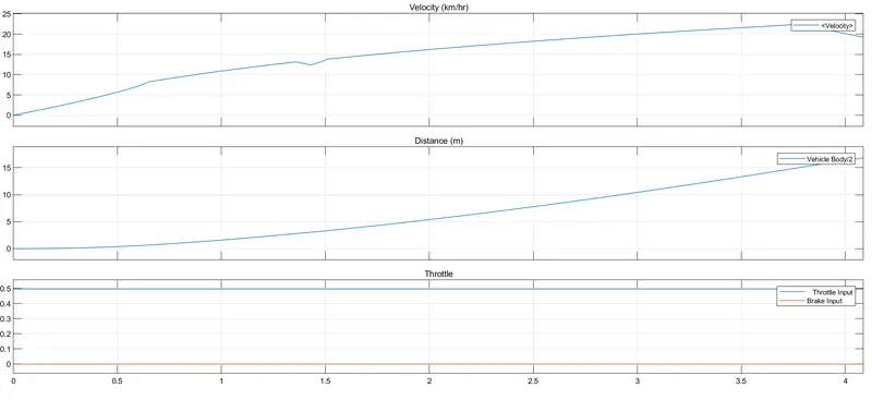
From the above graph, the throttle input is 0.5 given by the signal builder and also brake is 0. As the brake zero, then the velocity of the vehicle gradually increased from 0 to 55 kmph, and then it is constant. while velocity increases the distance traveled by the vehicle should increases.
Model 02 shaft speed:
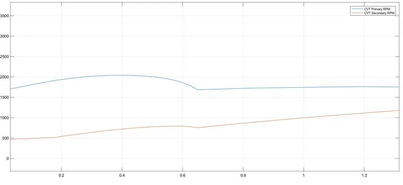
From the above shaft speed output, the values differ with respect to the gear ratio. It shows the variation of angular velocities of input and output shafts.
Speed vs torque ratio: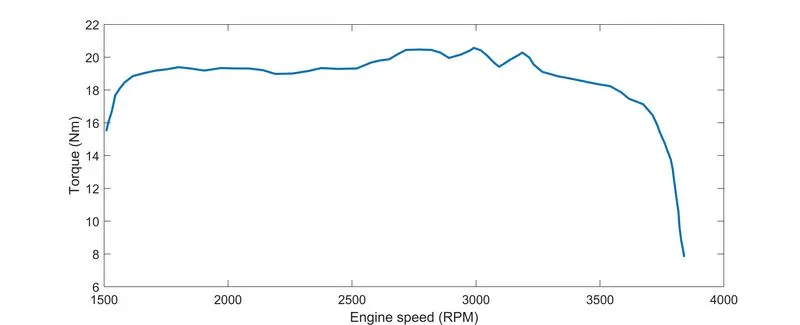
Model 03:
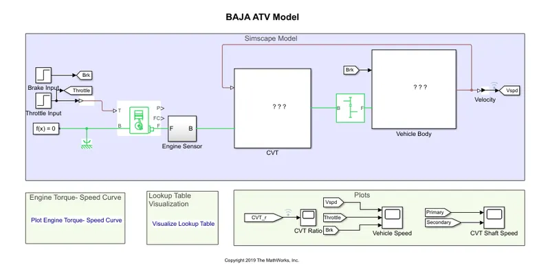
Simulink Model of BAJA ATV with CVT using Lookup Table:
Model 03 Output:
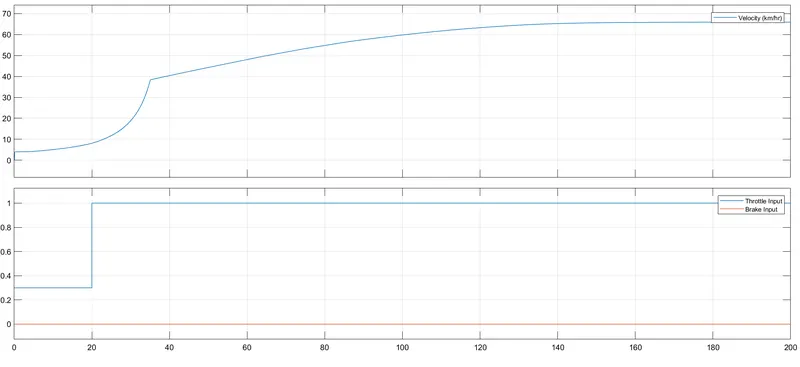
From the above graph, the throttle input is 0.3 to 1 given by the signal builder, and also brake is 0. As the brake zero, then the velocity of the vehicle gradually increased from 0 to 70 kmph, and then it is constant. while velocity increases the distance traveled by the vehicle should increases.
Model 3 Shaft Output:
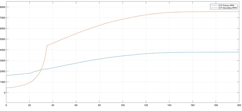
From the above shaft speed output, the values differ with respect to the gear ratio. It shows the variation of angular velocities of input and output shafts.
CVT Ratio:
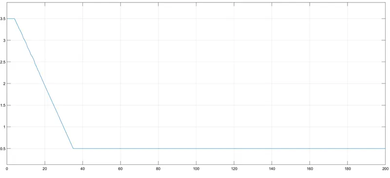
Model 04:
Simulink Model of BAJA ATV with CVT using Lookup Table with Dashboard:
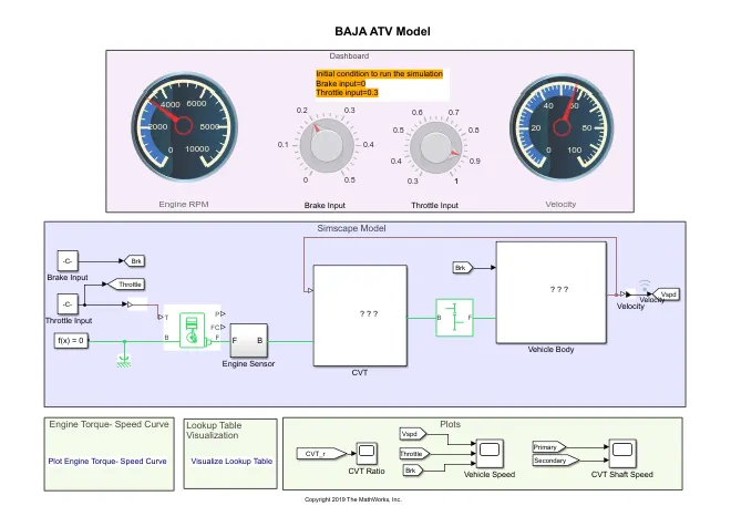
In this model, the CVT block is given with the CVT Ratio from the lookup table. Then the input Throttle and Brake is given by adjusting dashboard knobs.
Model 04 Output:
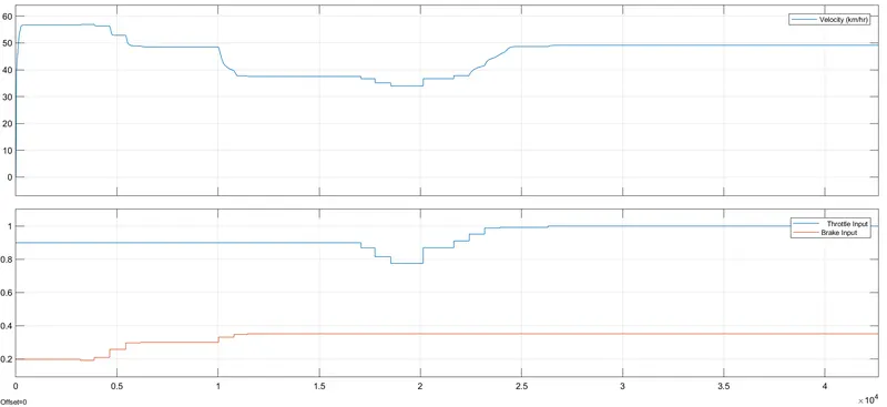
Here from the above graph the velocity of the vehicle gradually increases, then the brake and throttle input varies, the velocity gets reduced and maintain constant.
Model 04 Shaft Output:
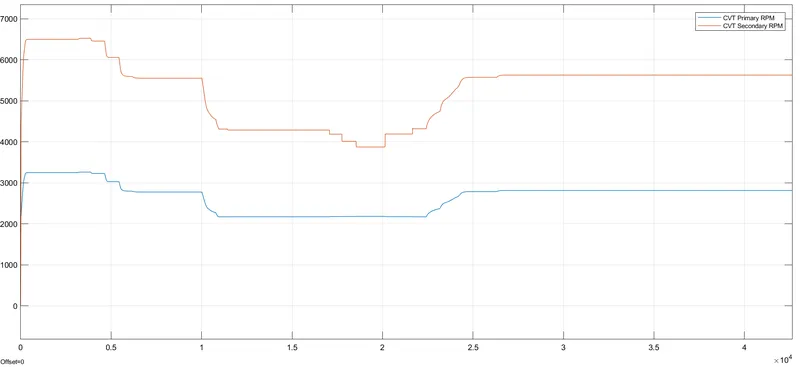
From the above shaft speed output, the values differ with respect to the gear ratio. It shows the variation of angular velocities of input and output shafts.
Result:
The observations from 4 different models of BAJA ATV with CVT, the velocity, throttle, brake, and shaft speed is successfully observed by varying values and recorded successfully.