Week - 4
1. Control logic of a “washing machine” using Stateflow
Aim:
To implement control logic of a “washing machine” using Stateflow.
Objective:
To implement control logic of a washing machine using Stateflow by achieving the following sequence,
- The system gets activated, when the power supply is available.
- Water supply is not available, stop the process & indicate through the LED.
- Soaking time should be 200s followed by Washing time of 100s.
- Then rinsing happens for the next 20s & dryer runs for 50s.
- Once all the processes have been completed turn on the End LED.
Procedure:
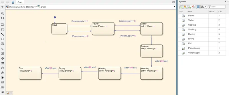
A washing machine is used to wash various types of clothes without applying any physical effort. The washing machine has two inputs, one is the power supply, which gives power supply throughout the machine and another one is the water supply, which provides the amount of water to be needed for washing clothes. The washing machine has four different stages of washing clothes. They are soaking, washing, rinsing, and drying.
Blocks used:
Charts - The chart block is a library file to implement Stateflow for any logic.
Constant - The constant is given as input to the Stateflow.
Display - This display block is used to observe the state of the output.
Lamp - The lamp is the dashboard kind of Simulink library block, used for the indication of output
Simulink Model:
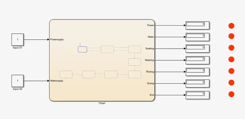
Stateflow diagram:
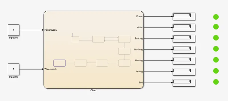
Powersupply and Watersupply as input and Every state of indication areas output.
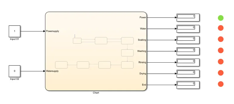
Power Supply ON:
When the input of powersupply is 1, then the machine switched ON. This is indicated as green by lamp 1.
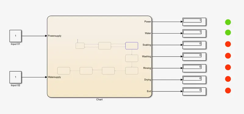
Water Supply ON:
When the input of watersupply is 1, then water is supplied to the machine. This is indicated as green by lamp 2.
Soaking:
The total simulation is running for 500 Sec. At first, the power supply is On at 10th sec and watersupply is ON at 20th Sec. Then at the 30th Sec, the machine started soaking. The soaking will happen for 200 Sec. This is indicated as green by lamp 3.
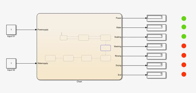
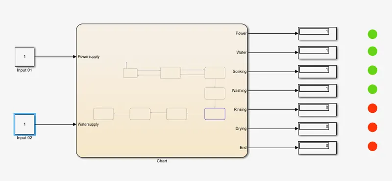
Washing:
The washing machine carried out the soaking for 200 sec, then the washing is started at 230th Sec as per the condition. Washing will happen for 100 Sec. This is indicated as green by lamp 4.
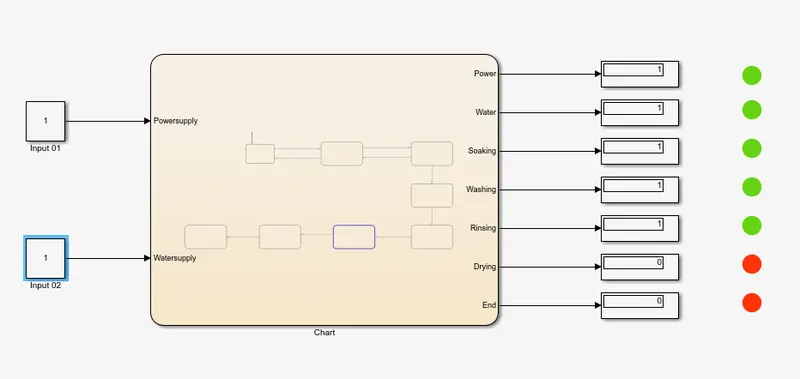
Rinsing:
After washing of clothes for 100 Sec, the removal of soap or detergent i.e, rinsing is done for 20 sec. The rinsing is done at 330th Sec as per the condition. This is indicated as green by lamp 5.
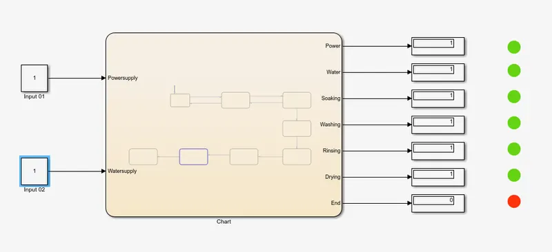
Drying:
After rinsing is done for 20 Sec, at the end of 350th Sec the drying of clothes was started. The drying will happen for 50 Sec. This is indicated as green by lamp 6.
End:
After the drying process, the clothes are ready to take out and all processes are done. This is indicated as green by lamp 7.
Result:
Every stage of input and output of the washing machine is implemented by a chart with Stateflow and successfully executed.
2. “Gear shift” logic
Aim:
To make a Simulink chart for the “Gear shift” logic with speed as input and display the gear number is transmitted.
Objective:
To make a Simulink model with a chart for the Gear Shift logic.
- To Make speed as input.
- To display gear numbers when the transmission is done.
Blocks used:
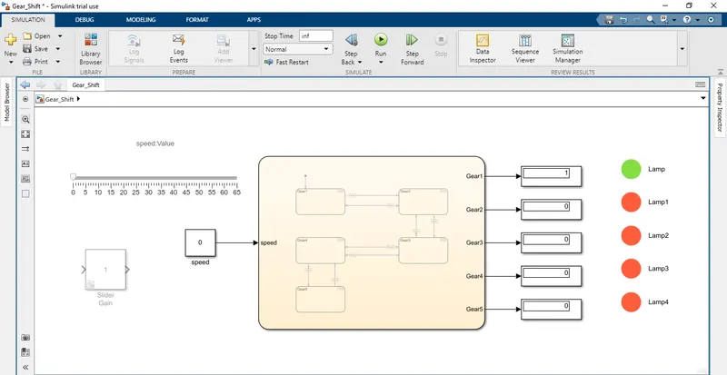
Slider - The slider block is a dashboard library from Simulink and it is used to give variable input to the constant. By using a slider we can give input to the constant while the simulation is running.
Chart - The chart block is a library file to implement Stateflow for any logic.
Display and Lamp - The display block is used to indicate the output, whereas the lamp indicates color according to the output.
Simulink Model:
Stateflow control logic:
Simulation:
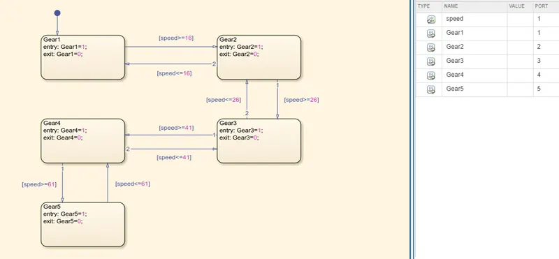
As per the condition, the speed is given as input and gear transmission is taken as output. The simulation time for the gear shift logic is given as infinite. so, that we can vary the speed by using a slider during the simulation. Here the speed is given as 0 to 15kmph, then Gear1 is active. It is indicated in the lamp.
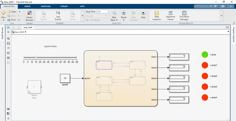
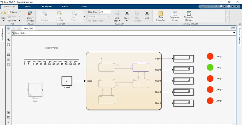
Speed: 16 to 25kmph
Then the speed increases above 15kmph, from 16 to 25kmph the Gear2 is ON. It is indicated in lamp 1.
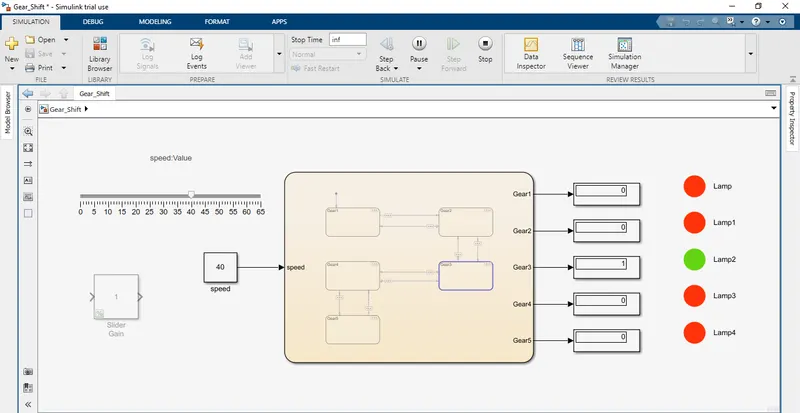
Speed: 26 to 40kmph
From 26 to 40kmph the Gear3 is active. It is indicated in lamp 2.
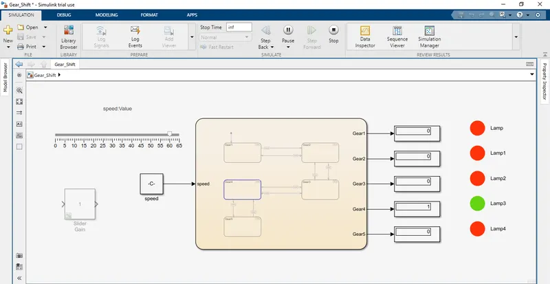
Speed: 40 to 60kmph
From 40 to 60kmph the Gear4 is active. It is indicated in lamp 3.
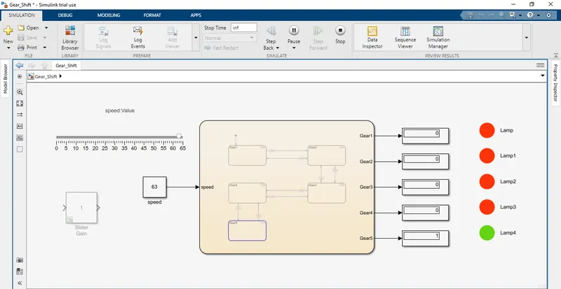
Speed: Above 60kmph
When speed increases above 60kmph, then Gear5 is active.
Result:
From the observation of input speed and output gears, the given condition is successfully executed and the output is indicated through lamps.