Week-7 Challenge: DC Motor Control
Answer -1
A.
Description -
The Bipolar Junction Transistor (BJT) when used for power switching applications, operates as an IGBT. When it is conducting (BJT operating in the saturated region), a forward voltage Vf is developed between collector and emitter (in the range of 1 V). Therefore, the IGBT block can be used to model the BJT device.
The IGBT block does not simulate the gate current controlling the BJT or IGBT. The switch is controlled by a Simulink® signal (1/0). The DC motor uses the preset model (5 HP 24V 1750 rpm). It simulates a fan type load (where Load torque is proportional to square of speed). The armature mean voltage can be varied from 0 to 240 V when the duty cycle (specified in the Pulse Generator block) is varied from 0 to 100%.
The H-bridge consists of four BJT/Diode pairs (BJT simulated by IGBT models). Two transistors are switched simultaneously: Q1 and Q4 or Q2 and Q3. When Q1 and Q4 are fired, a positive voltage is applied to the motor and diodes D2-D3 operate as free-wheeling diodes when Q1 and Q4 are switched off. When Q2 and Q3 are fired, a negative voltage is applied to the motor and diodes D1-D4 operate as free-wheeling diodes when Q2 and Q3 are switched off.
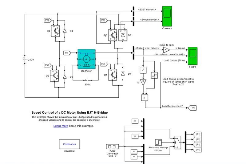
Initial Set of plots wihtout changing any parameters; Duty Cycle 75%
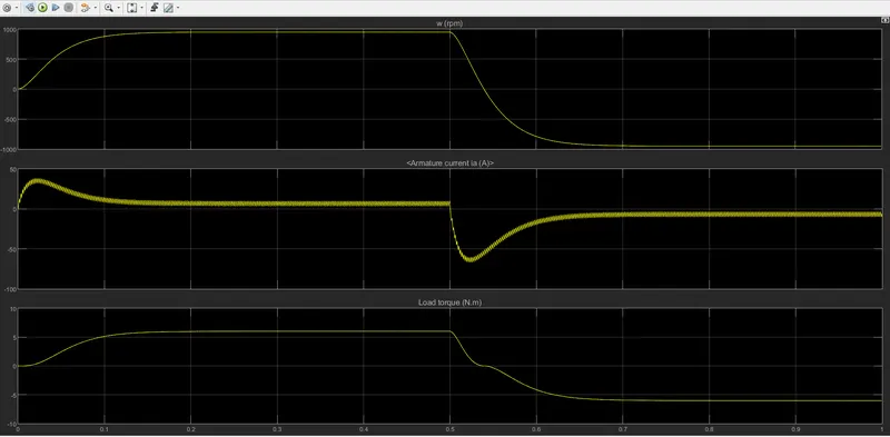
Changing the Duty Cycle in the Pulse generator to 50% and plotting the results;
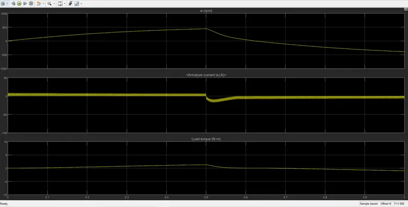
Changing the Duty Cycle again to 40% and plotting the desired reults;
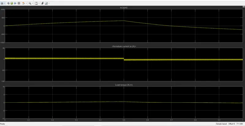
Changing the duty cycle to 25% and checking the desired plot;
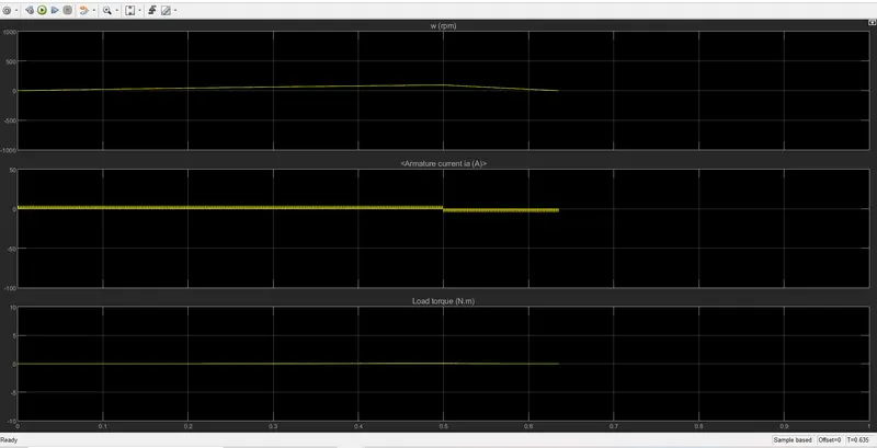
B. Inference - Armature Current Shoot up
- The first plot shows that the current shoot up is high and it receedes with time and becomes steady gradually.
- In the above three plots we can observe that as we decrease the duty cycle the noise in the particular plots decreases.
- Duty cycle refers to the amount of input sent to the motor at each cycle which consumes more energy and spikes the armature current.
- On switching up the motor the change in direction of the current eats up a lot of energy and the losses are also high. To minimise especially the heat losses, a heat sink is placed in use.
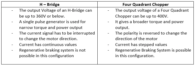
C. Comparison between Four Quadrant Chopper and H-bridge Model
Four Quadrant Chopper 200HP
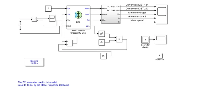
The 200 HP DC motor is separately excited with a constant 150 V DC field voltage source. The armature voltage is provided by an IGBT converter controlled by two PI regulators. The converter is fed by a 515 V DC bus obtained by rectification of a 380 V AC 50 Hz voltage source. In order to limit the DC bus voltage during dynamic braking mode, a braking chopper has been added between the diode rectifier and the DC7 block.
The first regulator is a speed regulator, followed by a current regulator. The speed regulator outputs the armature current reference (in p.u.) used by the current controller in order to obtain the electromagnetic torque needed to reach the desired speed. The speed reference change rate follows acceleration and deceleration ramps in order to avoid sudden reference changes that could cause armature over-current and destabilize the system. The current regulator controls the armature current by computing the appropriate duty ratios of the 5 kHz pulses of the four IGBT devices (Pulse Width Modulation). For proper system behaviour, the instantaneous pulse values of IGBT devices 1 and 4 are opposite to those of IGBT devices 2 and 3. This generates the average armature voltage needed to obtain the desired armature current. In order to limit the amplitude of the current oscillations, a smoothing inductance is placed in series with the armature circuit.
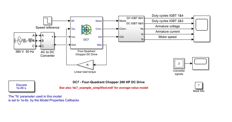
2. two quadrant chopper motor configuration from four quadrant chopper moto model in Simulink
To calculate the load torque charecteristics, we take the torque power equation of a vehicle and model the two quadrant chopper from a four quadrant chopper model.

Replacing the reference speed block with a block of column vectors which are "Drive Sync" values.
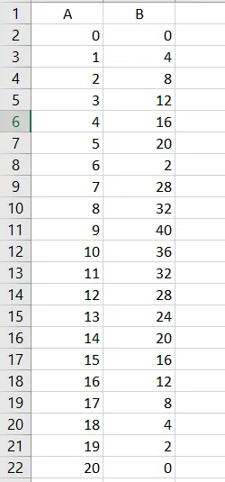
Additional Blocks used
- Dc battery
- Current measurement block
- Addition block
- Product block
- Square block
- Constant block for drive sync data
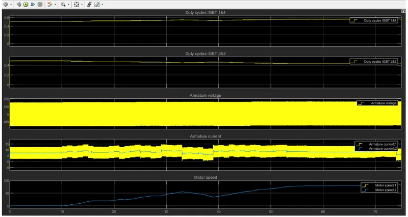
Plot
3. Operation of BLDC motor
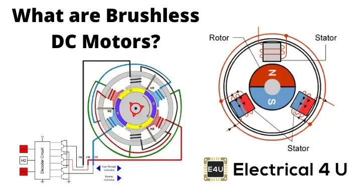
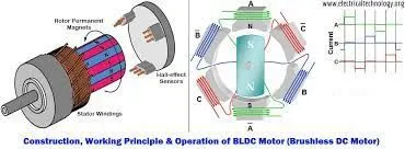
Brushless DC motors are also caleed as ECMs or Electronically commutated motors.The rotor is the sole bearer of the magnets in a BLDC and it doesn't require any power or any connections. Primary effciency is an important feature for a BLDC motor.BLDC motors employ along with controllers, rotary encoders or a Hall Sensor.
The main difference of a Brushed and a BLDC motor is the replacement of a mechanical commutator with an electric switch circuit. It is also a type of synchronous motorin the sense that the magnetic field generated by the stator and the rotor revolve at the same frequency.
BLDC motor works on the principle of a brushed motor. The Lorentz force law which states that whenever a current carrying conductor placed in a magnetic field, it experiences a force. As a consequence of the reaction force, the magnet will experience an equal and opposite force.
When the stator coil gets a supply from source, it becomes electromagnet and starts producing the uniform field in the air gap. Though the source of supply is DC , change in polarity makes it AC voltage Trapezoidal waveform. Due to the force of interaction between electromagnet stator and permanent magnet rotor, the rotor continues to rotate.
Reference -
robu.in
Matlab.com