Week 8 - Challenge 1 - Draft Analysis on a Fan Cover
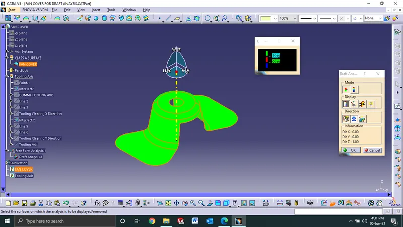
For 10 degree
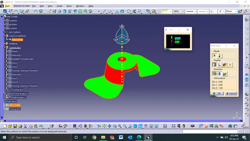
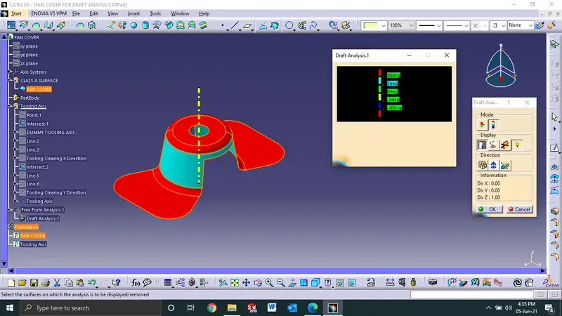
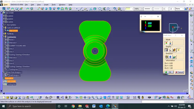
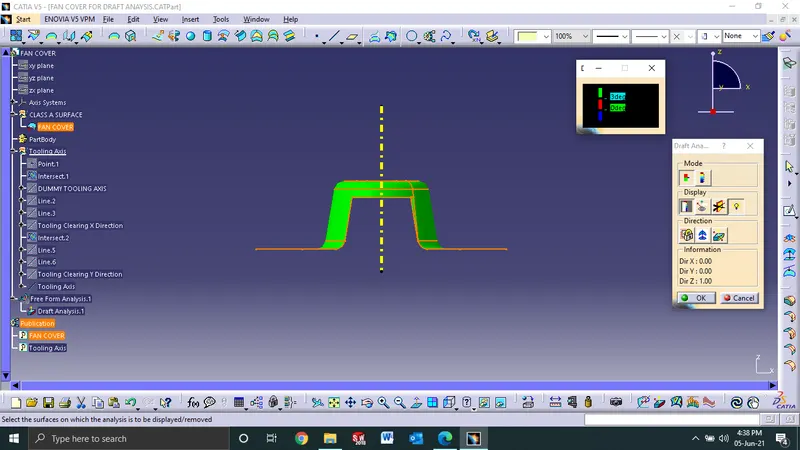
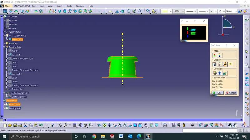
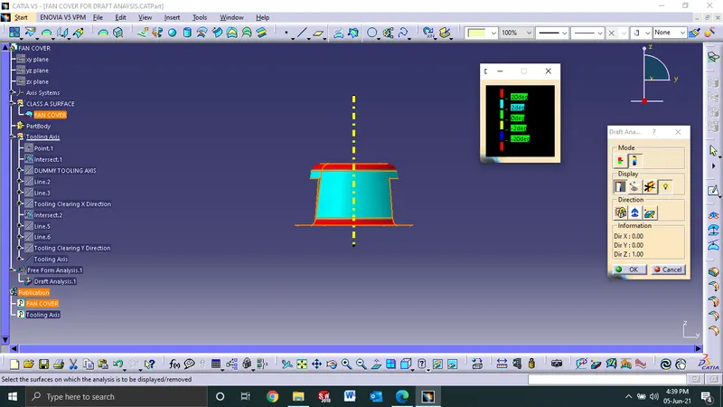
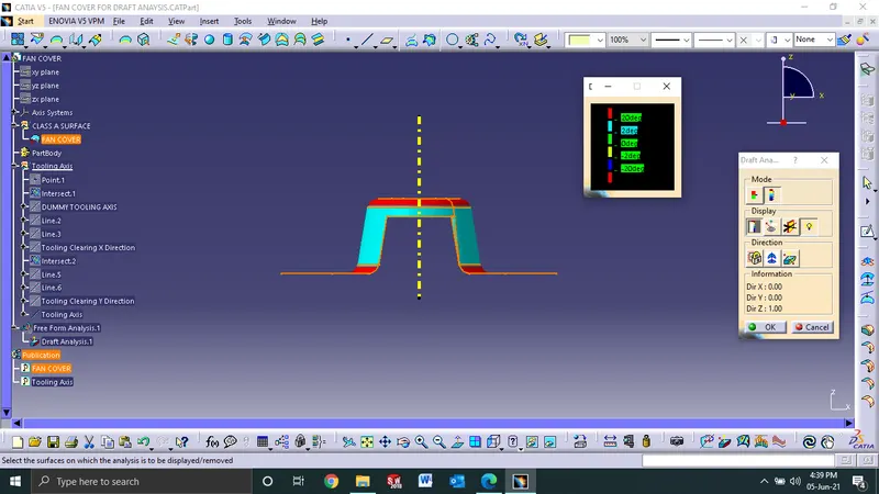
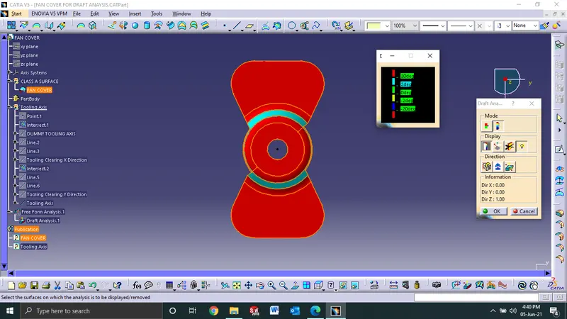
Draft Analysis Report and Tooling Axis Creation
In draft analysis;
- Firstly, the Class A surface is checked for any open ends. It is performed using 'Join' and after that 'Boundary'.
- A dummy Tooling Axis is created for reference.
- Intersect command is used to get intersection curves on XZ plane and the operatio is again repeated to get the same on YZ plane.
- Using the Intersection of XZ plane we create Tooling Axis in X-direction.
- The above process is repeated to get create Tooling Axis in Y-direction and on YZ plane.
- The bisection of both the axes obtained gives a single tooling axis.
- The fan cover Class A surface and the tooling axis is seperately published for better access.
- After all this the draft analysis is done on the class A surface.
- There are two modes: 'Quick Analysis Mode' and 'Full Analysis Mode'
- Under the quick analysis mode we have 3 colour codings out which if the draft has 0 degree it shows green, if it has negative value it turns blue and if it exceeds the given range of 2 degree or 3 degree(as we give as an input) it turn cyan.
- The full analysis mode however has more colour codings for different draft angles.
- To perform the analysis, we firstly lock the draft direction.
- Then we drag and place the compass on the tooling axis.
- We use the favourable mode of analysis and then we can also use 'Analyse under running point' for checkig the angles on the surface.
- We can also switch off the light efffect.
- To get a successful analysis we need a green output.
Tooling Axis Creation
- Firstly a point is defined centrally.
- A dummy axis is created on that point.
- Then we definne an Axis system on that point.
- The intersection between XZ plane and the Class A Surface is obtained.
- On that intersection we create reference lines on the angular bends by choosing point-point.
- After the creation we select bisecting method and create a bisection line out of those two angular lines Which becomes our Tooling Clearing of X-Axis.
- We repeate the same above process but now by intersecting the Class A Surface with YZ plane.
- We againn create two reference lines at an angle and then bisect those two lines again to obtain a refence line which becomes our Tooling Clearing of Y-Axis.
- No we again bisect 'Tooling Clearing of X-Axis' and 'Tooling Clearing of Y-Axis' to obtain our Final Tooling Axis of the Class A surface for molding.