Week-7 Challenge: DC Motor Control
Q:1a>: Speed control of a DC motor using BJT H-Bridge:
- this example aims to implement a Speed control mechanism using a chopped voltage using BJT H-bridge.
- The bipolar junction transistor (BJT) when used for power switching applications, operates as an IGBT. When it is conducting (BJT operating in saturation region), a forward voltage Vf is developed between collector and emitter in the range of 1V. Therefore, the IGBT block can be used to model a BJT device.
- DC motor used here in a DC machine. It implements a DC motor -either of wound type or permanent magnet type. For the wound-type DC machine, access is provided to the field connections so that the machine can be used as a separately excited, shunt connected, or series-connected DC machine.
- Initial parameters :
- Ra=2.581 ohms
- La = 0.028 H
- Rf = 281.3 ohms
- Lf = 156 H
- Preset Model is 01: 5HP 240 V 1750 RPM Field:300V
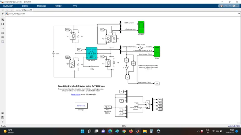
Fig:(a) Speed control of DC motor using BJT H-Bridge.
Input for gate terminals of all the 4 IGBT diodes is provided from a multiplexed circuit which consists of a pulse generator with a period of 2e-3. The armature voltage control is provided by a step block provided for 3 inputs and the condition used is U2>=Threshold.
H-Bridge circuit
This circuit is used for providing a constant DC-DC chopped voltage for a given application as used for speed control. It consists of 4 diodes connected at four corners of the arrangement of the circuit and the motor is placed in the center. Also at any given instant of time at least 2 of the 4 diodes need to be in the ON state. Diodes D1 and D4 are in the ON state for operating the motor in the forward direction. Similarly diodes D2 and D3 are connected for operating the motor in the backward direction.
Output Torque is given as T=Kw^2. So here Speed is given as an input to the math function-square block and then multiplied by a specific gain that is equal to k. In this case, the default value provided is 6.062e-4. IGBT current and Diode current are taken as outputs through diode Q3. Outputs of load torque, armature current, and speed are taken through the 'm' terminal of the DC machine. Load torque Tl is provided as an input for motor torque 'Tm'. Here the circuit voltage is 240V v DC.
Q:1:(b) Talking about the output waveforms for the H-Bridge, The 3 output waveforms are i]-Armature current (ia);
ii]: Load torque Tl and iii]: Speed. 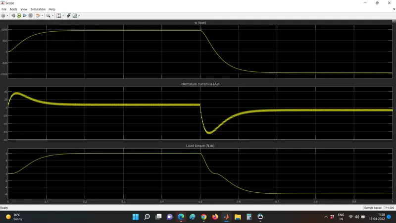
Fig b]: Armature current; load torque and speed of H-Bridge.
As seen from the above figure initially all the parameters are 0. The armature current is seen instantaneously increasing up to approximately 40 mA with fluctuations and decreases to approximately 15 -17 mA to a steady state for 0.5 seconds. Afterward, the armature current is negative for the rest of the period identical to a J-curve. Again increases to -10 A for another half cycle.
The speed 'w' is nearer to 1000 pm. Steady-state speed (synchronous speed) is achieved at 0.12 s. After the positive half cycle (forward motoring), the motor speed is accurately a mirror image of the forward motoring speed.
Talking about the torque, as we know the torque is proportional to the square of the speed. The torque also enters a negative value after the motor enters in the reverse direction. The peak value of load torque observed is 7-8 Nm. In the reverse motoring region, the torque value is -6 Nm respectively.
Q:1:c]- $$$$$$$$$$$$$$$$$$$$$$$DC_7$$$$$$$$$$$$$$$$$$$$$$$$$$$$$$$$
For opening the four quadrant chopper we need to type the command 'dc_7_example' in matlab command window.
Description:
The 200HP motor is separately excited with a constant 150v DC field voltage source. The armature voltage is provided by an IGBT converter controlled by 2 PI regulators. The converter is fed by a 515v DC Bus obtained by rectification of 380 V AC 50 Hz voltage source. To limit the DC bus voltage during dynamic braking mode, a braking chopper has been added between the diode rectifier and the DC7 block.
The first regulator is a speed regulator, followed by a current regulator. The speed regulator outputs the armature current reference used by the current controller to obtain the electromagnetic torque needed to reach the desired speed. The speed reference change rate follows acceleration and deceleration ramps to avoid sudden reference changes that could cause armature over current. In the H-Bridge circuit, all 4 chopper circuits were customizable. Also, the motor parameters could be changed to simulate different conditions. But the four-quadrants chopper drive single block has all the parameters of the motor as well as the H-bridge.
Q:2: MATLAB Model for two quadrant operation of DC motor
This model is implemented for speed control of a DC motor using PWM. The input to the DC motor is fed by the H-Bridge . H-Bridge has 4 inputs : REF,REV,PWM,BRK. If the REV port voltage is greater than the reverse threshold voltage,then the output polarit is reversed. If the BRK port voltage is greater than the braking threshold voltage, then the output voltage terminals are short circuited
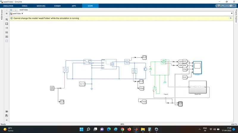
The outputs to the model are seen as below
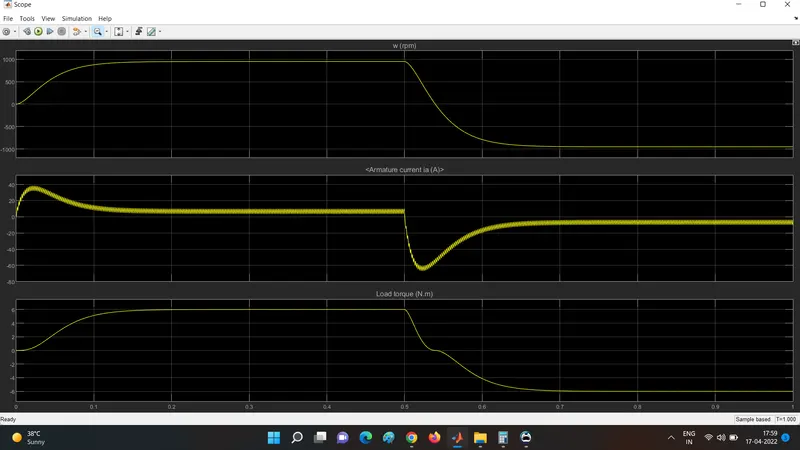
The quadrant of operation is decided by the direction of current and the speed of the motor.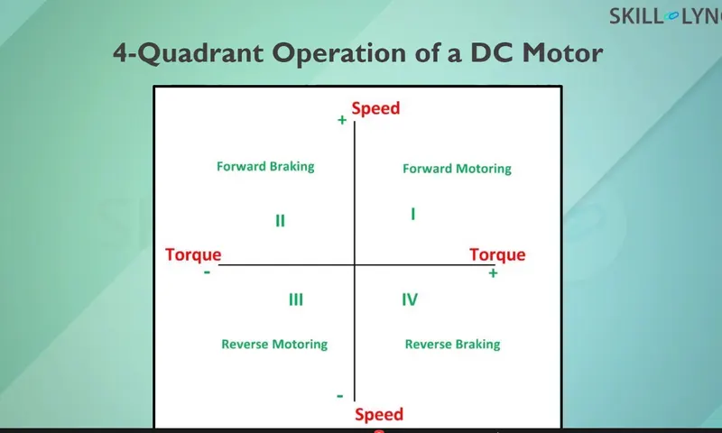
In this model at t=0.5 seconds the motor changes direction so it is operating in second quadrant. Initially the motor operates in first quadrant because the armature current is positive and load torque is greater than motor torque 'Tm'.
Q:3:- What is a brushless DC motor?
- A brushless DC motor is similar to a brushed DC motor but as the name suggests a BLDC doesn't use brushes for commutation but rather they are electronically commutated In conventional brushed DC motors, the brushes are used to transmit the power to the rotor as they turn in a fixed magnetic field.
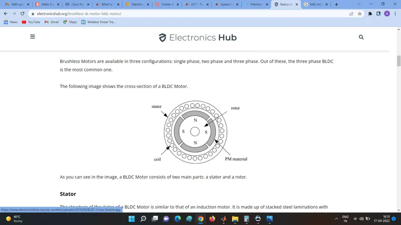 fig:c)construction of a bldc motor
 - The main design difference between brushed and brushless motors is the replacement of the mechanical commutator with an electric switch circuit.
- BLDC motor is a type of synchronous motor in the sense that the magnetic field generated by the stator and that of the rotor revolve at the same frequency.
- Brushless dc motors are available in three configurations: single-phase, two-phase, and three-phase. Out of this three, the three phases are the most common.
- stator: The structure of the stator is similar to that of an induction motor. It is made up of steel laminations with axially cut slots for winding. The winding in BLDC is slightly different than that of a traditional induction motor. Below fig shows the construction of the stator of a BLD motor.
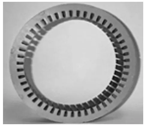
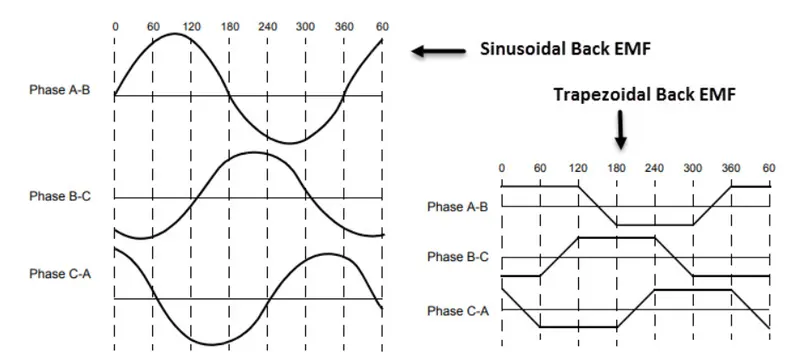
- Generally most BLDC motors consist of three stator windings that are connected in star or'Y' fashion (without a neutral point). Additionally, based on the coil interconnections, the stator windings are further divided into trapezoidal and sinusoidal motors.
 source:https://www.electronicshub.org/brushless-dc-motor-bldc-motor/
 - In the trapezoidal motor both the drive current and the back EMF are in the shape of a trapezoid (sinusoidal shape in the case of sinusoidal motors). Usually, 48 v(or less) rated motors are used in automotive and robotics (hybrid cars and robotic arms).
- Rotor: The rotor part of BLDC motors is made up of permanent magnets(usually rare alloy magnets like neodymium(Nd), Samarium Cobalt(SmCo), and alloy of neodymium, Ferrite, and Boron(NdFeB)).
- Based on the application, the number of poles can vary between two and eight with North (N) and South(S) poles placed alternatively. The following arrangements show three different arrangements of the poles. In the first case, magnets are placed on the outer periphery of the rotor.
- The second configuration is called a magnetic embedded rotor, where rectangular permanent magnets are embedded into the core of the rotor. In the third case, magnets are inserted into the iron core of the rotor.
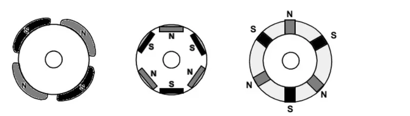
- Source:https://www.electronicshub.org/brushless-dc-motor-bldc-motor/
- Position sensors (Hall effect sensor):
- Since there are no brushes in the BLDC motor, the commutation is controlled electronically. To rotate the motor, the windings of the stator must be energized in a sequence and the position of the rotor (i.e.the north and south poles of the rotor) must be known to precisely energize a particular set of stator windings.
- A position sensor which is usually a hall sensor is generally used to detect the position of the rotor and transform it into an electric signal. Most BLDC motors use three hall sensors that are embedded into the stator to sense the rotor's position.
- The output of the Hall sensor will be either HIGH or LOW depending on whether the NORTH or SOUTH pole of the rotor passes near it. By combining the results from the three sensors, the exact sequence of energizing can be determined.
- Working:
- when current is applied through the coil, a magnetic field will be generated and the polarity of the field will be determined by the direction of the current flowing through the coil.
- Here the stator forms alternating pairs of poles and attracts the rotor pieces. To keep the rotor in motion the polarity of the stator is changed depending on the hall sensors.
- Advantages of BLDC motor are:
- No wear and tear due to the absence of brushes
- High efficiency
- Better speed vs torque characteristics
- Less noise or noiseless operation
- significantly higher RPM