Week-6 Challenge: EV Drivetrain
Q:1:There are 4 types of converters present in existence. They are i]Chopper[dc-dc converters];
2]rectifiers[ac-dc converters]
3]Inverters[DC-AC converters];
4]Synchronisers[AC-AC converters];
In most cases synchronisers are rare rest all circuits are identical in case of their orientation and connections in powertrain.
- In electric and hybrid electric rectifiers are used in the charging sockets where AC power needs to be strored in batteries as DC voltage supply.
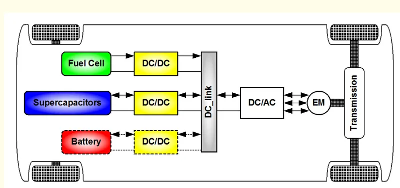
- The voltage stored in the batteries is in DC form and can't be supplied directly to motor-be it induction or brushless. To control the current and polarity inverter circuit is used in order to implement DC-AC conversion.
- Finally chopper is used in places where higher voltage DC needs to be converted to lower voltage or vice versa. A good example of step down chopper is regenerative braking where voltage is stored back in battery via DC-DC chopper. Addditionally there could be other power sources like supercapacitors, fuel cells etc. which are being considered for less bulky circuits.
Q.2: `omega`=((v/`kphi`)-(Ra/`kphi^2`))T-----------------(1)
given : v=72v
Ia=400a;
Ra=0.5;
kphi=0.7 v/s;
f=400hz;
duty cycle d2=70%;
As per the provided conditions , chopper is getting i/p voltage of 72v
Hence motor is getting 70% of 72 v;
Therefore va=50.4v.
substituting values eq (1) becomes: `omega`=(50.4/0.7 -0.5/`0.7^2`)*Tv
`omega`/Tv=(50.4/0.7 -0.5/0.7^2);
1/Tv=(50.4/0.7-0.5);
Tv=`omega`/70.98;-----------------------------------(2)
given equation is Tv=24.7+(0.0051)`omega^2`-----------------------------(3);
substituting eq(2) in eq(3) we get;
`omega`=1753.206+0.361998`omega^2`
0=0.361998omega^2-omega+1753.206;
solving for w we get omega1=1.381223 &omega2=1752.5153.
but this speeds are in rad/s ;to get speeds in rpm we need to multiply them 60/2*pi;
now omega1 in rpm=13 and omega2=16743rpm which is the required speed
since omega 1 is not coinciding with given values only omega2 is valid i.e.16743rpm.
Q.3:
Mathematical model of DC motor for equation : (V/kphi -Ra/`kphi^2`)*T
- Usually first the derivative quantity needs to be recognised. Here the derivative quantity could be `omega`= `d theta /dt`. So I first simplified the torque quantity in terms of general formula that is `tau`= f x r;
- Here force = m*a=m* d`d^2 theta/dt^2`.
- From the equation provided in the assignment help video it consisted of 2 equations as follows;
- dia/dt=1/La(Vin-iaRa-ke*dtheta'a'/dt) & d2theta/dt^2=1/Jm(kt*ia-bmdtheta'a'/dt)r
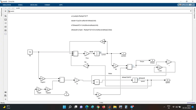
- As seen in the image above there are 2 inputs :1-Armature resistance Ra and 2- armature voltage. Since there are 2 equations being used so i used 2 adder blocks. Gain block is used for introducing different variables. Integrator block is used here for getting the differential quantities. output is taken through 3 terminals a-current,b-torque,c-speed.
- The corresponding outputs are as shown below:
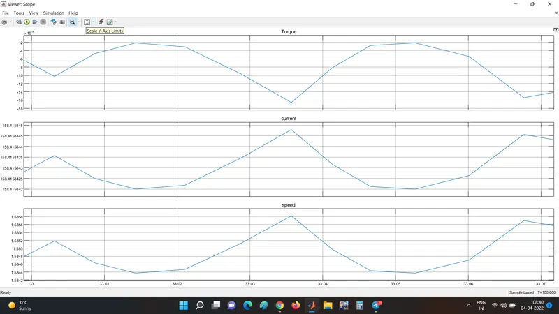
- From the output it is evident that the torque and speed produced are with a lot a ripple or irregularities. The torque is produced higher at lower speeds and lower at higher speeds respectively. Speed and current seem to be directly proportional.
Q.4:
The article is a detailed comparison between induction motors and dc brushless motors. Talking about the author -"Wally Ripple " he was an engineer at 'tesla motors'. Before that, he was also an engineer at general motors at aerovironment where he worked for developing EV1 model. Which makes it perfect to explore his perspectives and experiences regarding dc motors and induction motors.
- One size does not fit all there is no so-called "the best" piece of equipment in terms of technology, it always changes or rather upgrades gradually or sometimes instantaneously. To explain this in terms of cars the author has explained how different milestones were achieved. Initially, there were flathead engines, followed by Hemis, straight, opposed and the recent one is the V configuration.
- In olden times (4 decades approximately) there were lead batteries, brushed motors, contact controllers, which are currently seen replaced by lithium batteries, brushless DC motors, and inverter drives for controlling. The overall conclusion comes that there is no best engine instead there are specific engines that fulfill personal requirements like performance and price.
- Brushless machines consist of two or more permanent magnets on the rotor which provide DC magnetic field. In turn, this DC magnetic field is cut by the stator core and a torque action is produced. For things to function in equilibrium three things need to be taken into consideration a)current direction should be instantaneous with the rotor,b)torque must remain constant and c)The conversion of electrical energy should be efficient. To maintain the polarity and magnitude special circuit known as an "inverter" is used. Without inverter, the BLDC can't be controlled.
- In the case of an induction motor the stator is virtually (theoritically) identical, except there are no magnets on the rotor . The conductors provided are attached to the outer covering of stator and act as a magnet. The best advantage of induction motors is that they can easily adapt to the common 3-phase supply voltages and work well even in load conditions.
- Induction motors cannot function on DC directly. They only need AC or an inverter connected to an AC source that could be used for powering an induction motor. The only limitation of an induction motor is that it has a limited range of peak torque values and limited starting torque.
- Brushless DC motors need a power source whose phase is maintained at a constant magnitude proportional to the rotor points.
- In order to implement induction motors in place of DC motors or DC brushless motors, the feedback loops must be connected in such a way that it produces the same input frequency that the motor desires.
- The advantage of DC brushless motors is that since there is no physical connection between stator and the rotor they are magnetically coupled circuits and hence there cooling is easy leading to improvised efficiency than induction motors.
- Both DC and induction motor drives have same type of stator and have same 3 phase inverter drives. The only differences are the inverter controls and the rotors. And with digital controllers the only differences are with control code.
- In an ideal brushless drive the strength of the magnetic field produced would be adjustable. When maximum torque is required -especially at loww speeds-the , magnetic field strength should be maximized. This is done to reduce the inverter currents and motor currents are maintained at the lowest possible values. This gives the advantage of reducing the `I^2R`losses that consequently help to increase the efficiency.
- When torque levels are low the magnetic power losses needs to be low leading to low hysterisis and eddy losses. The only problem is that there is no method of adjusting magnetizing power with the use of permanent magnets.
- In contrast the induction drives are adjustable as there is no permanent magnet involved and can be easily achieved by altering the v/f ratio.
- Induction drives are used in high power applications and brushless motor drives are used for medium power ranges.
- Induction drives is more cost efficient as there is no permanent magnet in the motor but only problem encountered is that the forces acting on a induction drive are complex. So the brushless motor drives and induction motor drives are best for their own applications in the field of hybrid electric and pure electrics.