Week-7 Challenge: DC Motor Control
1. A. Explain a MATLAB demo model named ‘Speed control of a DC motor using BJT H-bridge’.
Answer:
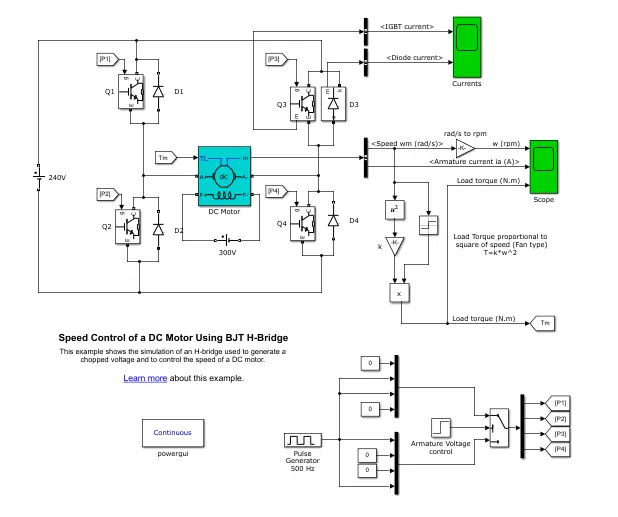
The Speed Control of a DC motor using the BJT H-bridge demo model is shown below. This model is used to produce a chopped voltage & speed control of the DC motor.
H-bridge:
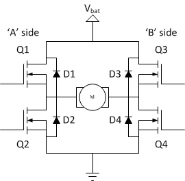
H-bridge is an electronic device that controls the direction in which the motor rotates & its speed. H-bridge consists of four IGBT & a load is connected in the center. Here IGBT works as power switching BJTs. To invert the 0-240v DC supply 4 switches are used. Current flowing from collector to emitter
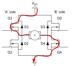
In the above-shown figure, the switch Q1(A side) switch Q4(B side) is turned on. So Current starts flowing from positive potential through the switch Q1 to the load then through switch Q2 to a negative potential completes the circuit. Let's consider motor is running in the positive direction in this mode.
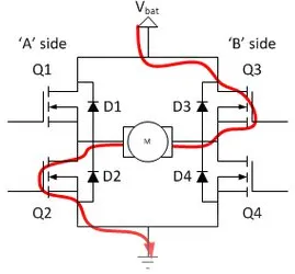
In the above-shown image, the switch Q3(B side) switch Q2(A side) is turned on. So Current starts flowing from positive potential through the switch Q3 to the load then through switch Q2 to a negative potential completes the circuit. In this case, motor terminals are connected in opposite compared to the previous mode. so the motor rotates in the opposite direction now.
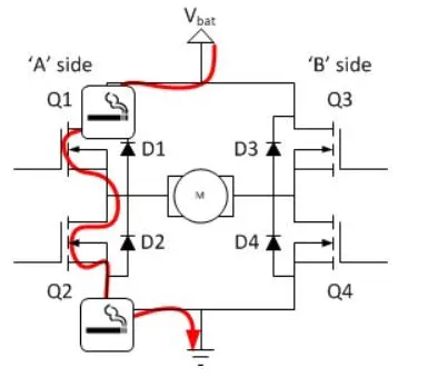
If switch Q1 & switch Q2(A side) are turned on this will create the least resistance path in the circuit, resulting in a short circuit. Similarly on the B side for switch Q3 & Q4. To prevent a short circuit in any case switches from the same side should not turn on.
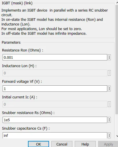
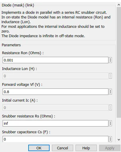
The IGBT parameters are as follows. And Diodes are configured as freewheeling diodes.
DC motor:
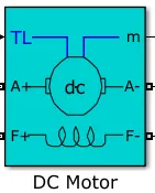
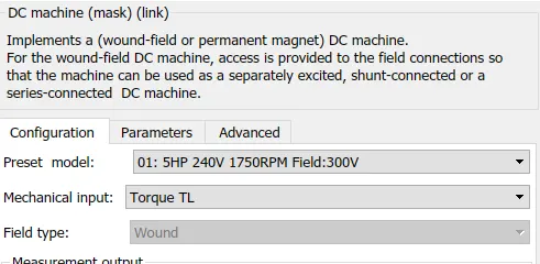
This motor can be modeled as a permanent magnet or wound field DC motor. In this model, it is used as a wound field DC motor by providing power to the field connections. Here the motor model is 5HP, 240V, 1750RPM, & field:300V.
Working:
The speed of the motor can be controlled in 3 ways.
- By changing the flux & changing the field winding current.
- By changing the armature voltage & armature resistance.
- By supply voltage.
In this model pulse generators are used to change the armature voltage to control the speed of the motor.
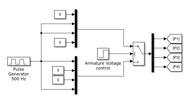
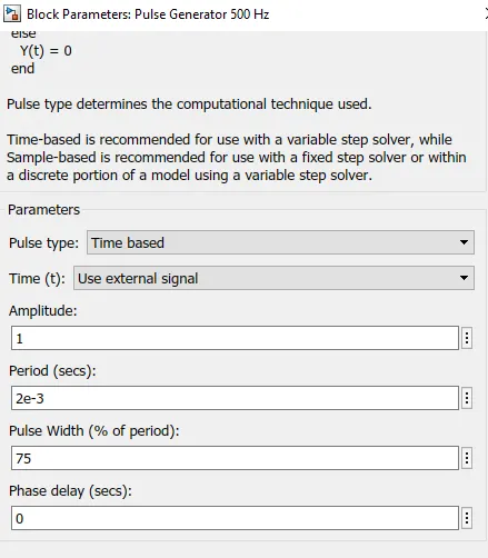
The pulse generator parameters are as shown below. 75% of the duty cycle specified in a pulse generator, the pulses P1, P2, P3 & P4 are connected to the gates of Q1, Q2, Q3 & Q4 accordingly, to vary armature voltage.
Results:
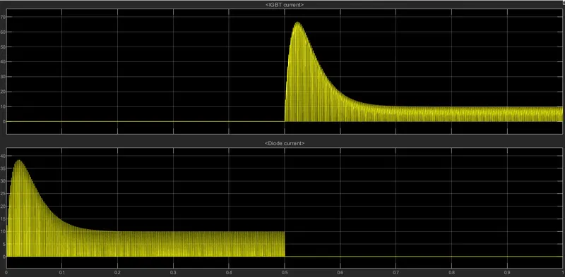
The below image shows the current in IGBT(Q3) & Diode(D3) for 0-1 sec. 0-0.5 sec current flows through D3 & 0.5 to 1-sec current flows through Q3. The motor starts rotating in the positive direction for a duty cycle of 75%(ie 180V) till 0.5 sec, after the armature voltage is suddenly reversed motor runs in the negative direction.
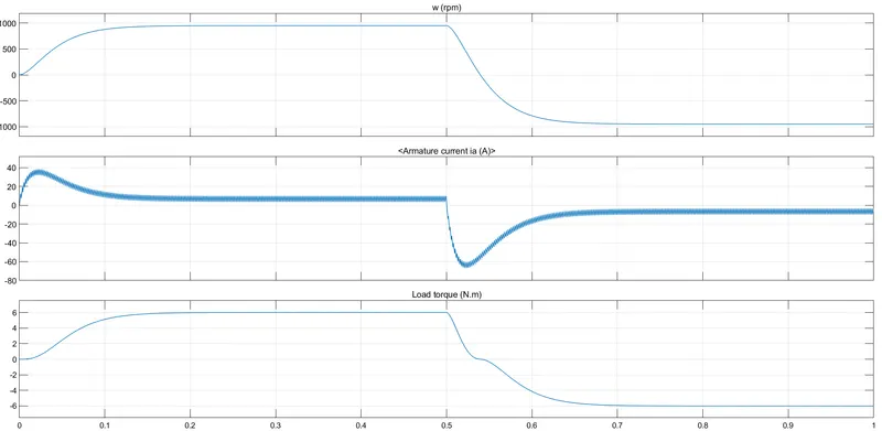
Motor speed, armature current & load torque are shown below.
For 0-0.5 sec the rpm gradually increases from 0-900 rpm. From 0.5-1 sec, the rpm gradually increases from 0-900 rpm in the negative direction.
B. Comment on the armature current shoot-up from the scope results.

From the armature current graph, it is observed that a sudden spike during the transition at 0 sec & 0.5 sec. Huge surge in current during this period. To minimize this sudden shoot-up in current by changing the duty cycle. Let's change the duty cycle from 75% to 50% & the results are as shown below.
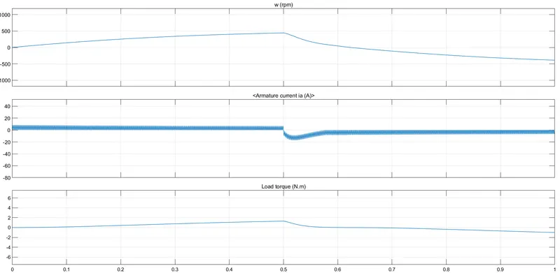
Let's change the duty cycle from 50% to 35% & the results are as shown below.
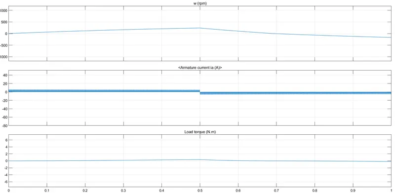
It is observed that by changing the duty cycle armature current shoot-up can be reduced.
C. Refer to the help section of ‘The Four-Quadrant Chopper DC Drive (DC7) block’. Compare it with the H-bridge model.
Answer:
The four-Quadrant Chopper circuit is shown below.
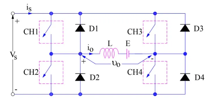
The above-shown circuit is the four-quadrant chopper or Class-E chopper. It includes four switches(CH1,CH2,CH3 & CH4) & 4 diodes (D1,D2,D3 & D4). These diodes are connected anti-parallel to the switches. The operation of switches in the different quadrants is shown below.
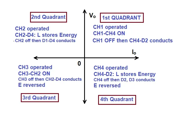
- In the 1st quadrant, CH1 is operated & CH4 is on. current flowing from the source to the load & Vs = Vo. when CH1 is turned off current flows through CH4 & freewheel diode D4. The voltage & current are still positive. So the operation is in known as forward motoring.
- In the 2nd quadrant, CH2 is operated & keeping all other switches off. The DC source on the load drives the current along with CH2, D4, E & L. Inductor stores energy during this period. When CH2 is turned off current starts flowing through D4 & D1 to the source. Now E+L*di/dt is more than Vs. So power is feeding back to the source. This operation is known as forward braking.
- In the 3rd quadrant, CH3 is operated & CH2 is on. The polarity of E is changed when the current starts to flow from CH3 to load across CH2. When CH3 is turned off current flows CH2 & freewheel D4 So Vs = -Vo since both voltage & current is in the negative direction, this operation is known as reverse motoring.
- In the 4th quadrant, CH4 is operated & keeping all other switches off. Now current starts to flow through CH4, D2, L & E. When CH4 is off current flows through D2 & D4 and is fed back to the source. Now load current is positive & voltage is negative. This is known as reverse braking.
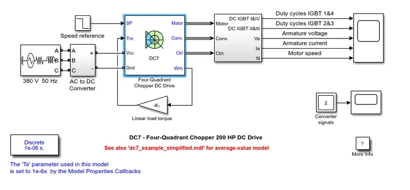
The simulation model of the Four-Quadrant Chopper DC Drive (DC7) block is shown below.
Working:
- The DC7 blocks represent the four-quadrant chopper.
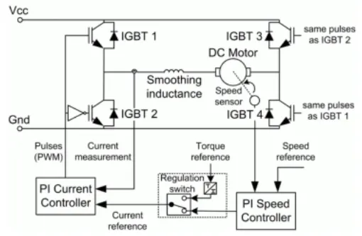
- Pulses are given to the switches from the PI current controller, by comparing the reference current & armature current.
- Reference current can be calculated by torque reference & PI speed controller in the regulation switch.
- PI speed controller calculated by comparing motor speed & input reference speed. Speed is controlled by the current controller.
- In this drive, the motor can be rotated in all 4 quadrants as explained above.
Simulation result:
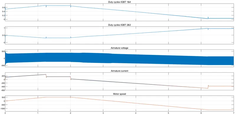
- The Armature current follows the reference path with no shoot-up/spike in current.
- The motor is coupled to the linear load, mechanical torque is proportional to the speed of the motor.
Comparison:
H-bridge:
- Open-loop working mechanism.
- Can operate in forward motoring & reverse motoring.
- Changing direction by changing the current polarity.
- Can be operated with the generated signal. Used in robots.
- Efficiency is more due to high switching frequency.
Four-quadrant:
- Close loop working system.
- Can operate in forward motoring, reverse motoring, forward braking & reverse braking.
- Changing the direction using current signals.
- Used in industrial applications & high powering applications.
- Efficiency is less compared to class E chopper.
2. Develop a 2-quadrant chopper using simulink & explain the working of the same with the relevant results. (Refer to article - Multiquadrant operation of motor )
Answer:
2-quadrant chopper circuit diagram as shown below.
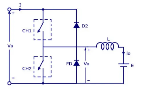
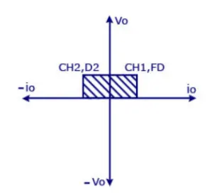
The 2-quadrant chopper is also known as a Type C chopper. In this type, during both quadrants, the voltage remains positive. And a freewheeling diode is placed across the load. In the first quadrant, CH1 is on & CH2 is off, current starts to flow through CH1, L, E. If CH1 is off, the inductor discharges through FD(L-E-FD-L). The output voltage is equal to Vs, so both voltage & current will be positive. When CH2 is on & CH1 is off, current flows from E, L, CH2 & E. If CH2 is off, current flows through D2 to the source(E-L-D2-E). Regenerative braking occurs in the 2nd quadrant as shown below.
The Simulink model is shown below.
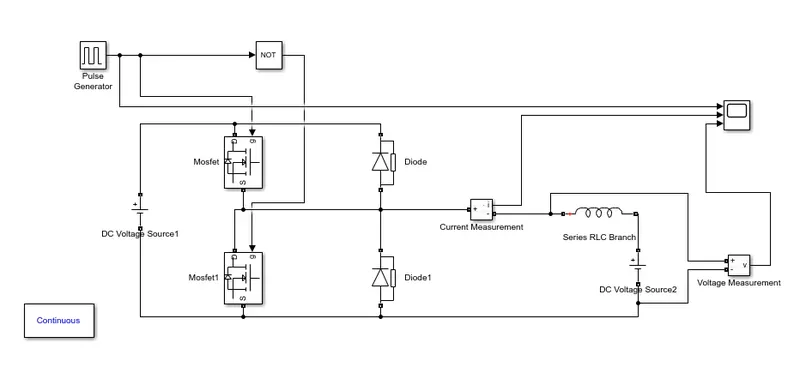
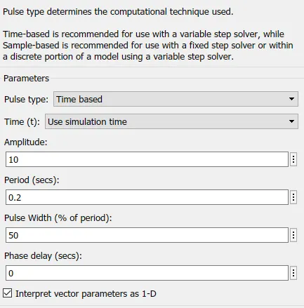
The DC voltage source1 is set to 24V & DC voltage source2 is set to 12V. Pulse generator parameters are shown below. In the above figure, RLC & voltage sources represent the motor.
Simulation results are as follows.
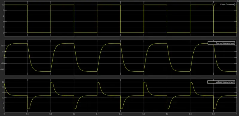
Here the voltage always remains positive. Current varies from positive to negative.
3. Explain in a brief about operation of BLDC motor.
Answer:
- BLDC motors are commonly known as Brushless DC motors. Unlike the normal DC motor which uses Brushes & commutators to excite the rotor, brushes & commutators are not applicable here.
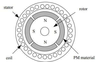
- The most advantage of these motors are rotor does not require any power. These motors are types of synchronous motors, here the stator magnetic field and permanent magnet rotors are almost synchronous to each other.
- Stators are electromagnets excited by windings and coils around them.
- Rotors are implemented with permanent magnets. It can vary from 2 poles to 8 pole pairs with alternate north & south poles. To obtain more torque, the flux density of the material should be high.
- These motors can be constructed in different configurations based on the requirements. Depending on the stator winding this can be classified as a single-phase, 2 phase, and so on. Normally 3 phase motors are commonly used.
- BLDC motor works on the same principle as the Brushed DC motor. in these motors, current-carrying windings are in the stator and permanent magnets are in the rotor.
- When DC supply is given to the stator windings it becomes the electromagnet and produces a uniform field in the air gap.
- Though the supply is DC, switching makes to generate an AC voltage waveform. Due to the force of interaction between the stator and rotor, the rotor continues to rotate.
- With the switching of the windings as high and low signals, corresponding windings are energized as north and south pole.
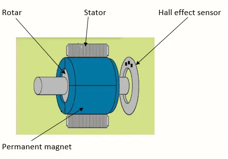
- The hall effect sensor provides information on the position of the rotor. This sensor helps to synchronize the rotor position with stator armature excitation. since BLDC motors are controlled electronically, stator windings are energized in sequence in order to rotate the motor.
- The layout of the BLDC motors can be varied depending on the placement of the rotor and stator.
- Outrunner: The field magnet is a drum rotor that rotates around the stator. These are applicable where high torque & low rpm is required.
- Inrunner: Here stator is a fixed drum in which the field magnet rotates. These are applicable where high rpm & low torque are required.
Advantages:
- Overall maintenance is less due to the absence of the brushes.
- Produce no noise due to the absence of the brushes.
- Less electromagnetic interference.
- High efficiency & high output power to size ratio due to the use of permanent magnets rotor.
- Long life span.
- Can be operated in flammable environments.
- More reliable.
Disadvantages:
- These motors are expensive.
- An electronic controller is needed to control the motor.
- Complex drive circuitry.