Project
Aim: To carry out a system-level simulation of an all-terrain vehicle(ATV) for different cases.
Objective:
- The primary objective is to study the Baja ATV Simulink model with & without the dashboard system.
- The secondary objective is to study the Baja ATV Simulink model using the lookup table data with the dashboard system.
Chapter-1
Introduction
In a vehicle, a transmission is a medium that transmits the power produced by the engine to the rotating shaft.
Types of transmissions are
- Manual Transmission
- Semi-Automatic Transmission
- Automatic Transmission
- Continuously Variable Transmission
- Dual-Clutch Transmission
CVT is a Continuously Variable Transmission, Which consists of 2 Conical pulleys at the driver & driven shaft and a steel belt. The output speed mainly depends on the width between the two conical pulleys. If the distance between the driver pulley is more than the distance between the driven pulley, then the output shaft speed is less. If the distance between the driven pulley is more than the distance between the driver pulley, then the output shaft speed is more. This mechanism provides the countless gear ratio to the CVT. CVT can maintain a constant engine RPM so the fuel efficiency will be more.
Some of the commonly used blocks in all modules:
1. Generic engine block:
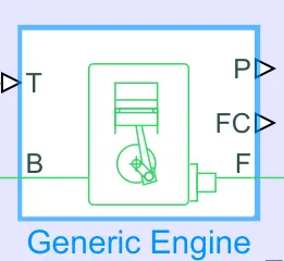
Represents a system-level model of spark-ignition and diesel engines suitable for use at the initial stages of modeling when only the basic parameters are available. T is the Physical throttle input signal that lies between zero and one and specifies the torque demanded from the engine as a fraction of the maximum possible torque. B & F are rotational input & output conserving ports that indicate the engine block & engine crankshaft respectively. P & FC are physical signal output ports that represent the engine power and fuel consumption rate respectively.
2. Engine sensor sub-system block:
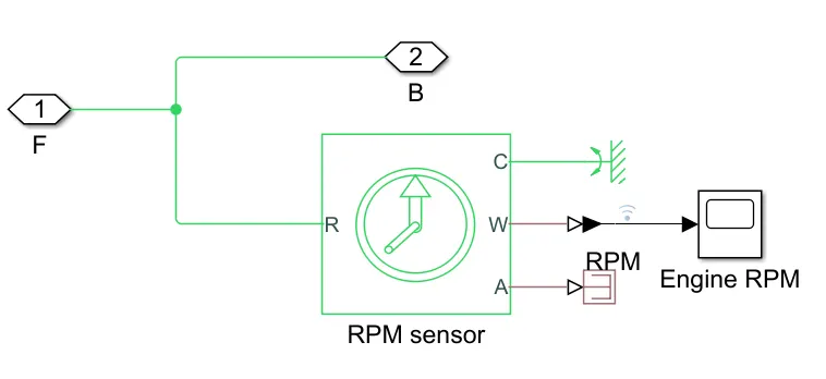
Measures the output of the engine RPM. The rotational motion sensor is the block that measures angular velocity or angle in a mechanical rotational network. The physical signal ports W and A measure the angular velocity and angle respectively. C is connected to the mechanical rotational reference.
3. CVT sub-system block:
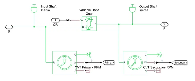
Variable ratio transmission represents a variable ratio gearbox as implemented by mechanical belt CVT. The physical signal input r defines the ratio of input to output angular shaft velocities. Both Base pulley & Follower pulley are connected to ideal rotational motion sensor & mechanical rotational inertia. The follower pulley is connected to the Simple gear block.
4. Simple Gear block:
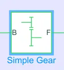
Represents a fixed-ratio gear or gearbox. No inertia or compliance is modeled in this block. Considered Follower (F) to base (B) teeth ratio as 10.
5. Vehicle body sub-system block:
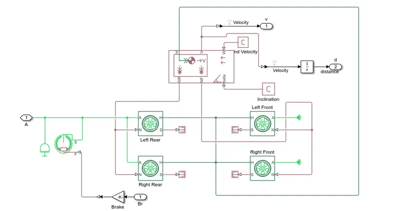
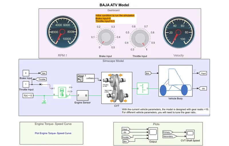
The vehicle body sub-system consists of an ideal mechanical rotational inertia, Double-shoe brake block arranged as two pivoted rigid shoes symmetrically installed inside or outside a drum and operated by one actuator. The actuator force causes the shoes to exert friction torque on a shaft connected to the drum. Connection S is a conserving rotational terminal associated with the drum shaft. Connection F is a physical signal port representing the force input to the actuator. Tire block represents the longitudinal behavior of a highway tire characterized by the tire Magic Formula. Connection A & H are the mechanical rotational conserving port for the wheel axle & wheel hub through which the thrust developed by the tire is applied to the vehicle respectively. Connection N is a physical signal input port that applies the normal force acting on the tire. Connection S is a physical signal output port that reports the tire slip. A vehicle body block is a two-axle vehicle body in longitudinal motion. The block accounts for body mass, aerodynamic drag, road incline, and weight distribution between axles due to acceleration and road profile. Connection H is the mechanical translational conserving port associated with the horizontal motion of the vehicle body. Connections V, NF, and NR are physical signal output ports for vehicle velocity and front and rear normal wheel forces, respectively. Connections W and beta are physical signal input ports corresponding to headwind speed and road inclination angle, respectively. The mass of the vehicle is considered as 250 kg.
Chapter-2
case 1: Baja AVT model without a dashboard
Input signals:
Signal builders are used to generating the input signals for Brake, Throttle & CVT ratios as shown in the below images.
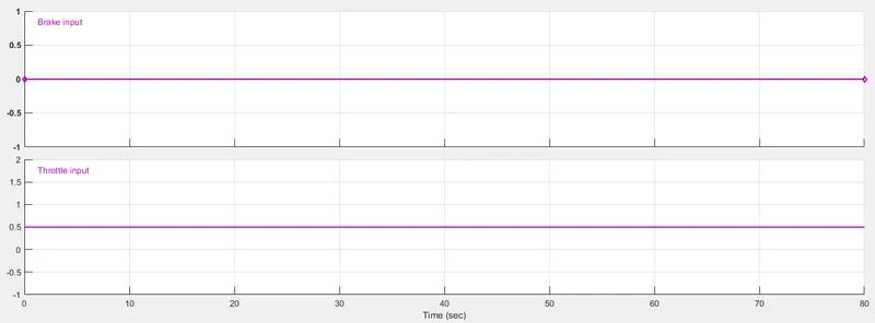
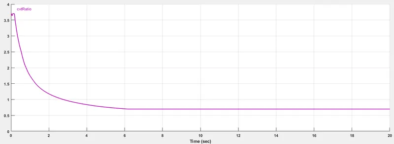
From the above images, it can be observed that the Brake input is 0 & the Throttle input is 0.5 throughout the time. The Throttle controls the fuel flow rate to the engine. The CVT ratio decreases exponentially from around 3.6 at 0 sec to around 0.6 at 6 sec & remains constant.
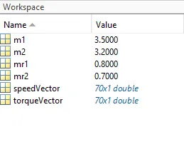
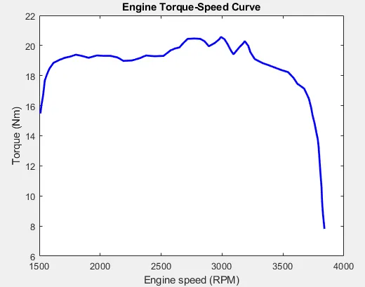
m1 & m2 are used as the mass inputs for the ideal mechanical rotational inertia. The speedVector & torqueVector are used in Generic engine parameters. The torque vs speed curve is shown below.
Working principle:
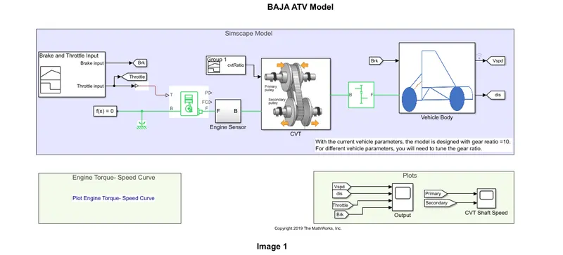
The throttle input from the signal builder is passed to the engine. The engine output is connected to the RPM sensor, to collect the engine RPM data. Then it is connected to the CVT block. Here the CVT block has 2 inputs one from the engine & another from the signal builder CVT ratio. The variable gear ratio changes its gear ratio during the simulation as per the CVT ratio input. CVT block output is connected to the simple gear block. The output of the simple gear block is connected to the Vehicle body block, this block has another input from the signal builder brake input. Since the model considered is a two-wheel-drive vehicle, the input signal from the simple gear is connected to both rear wheels. Along with that, the Brake input is also connected to both rear wheels. And Vehicle body block provides the Velocity & distance as output. So after a simulation of 200 sec, the following results are obtained.
Result analysis:
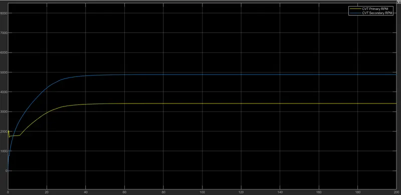
The initial velocity of the CVT primary shaft is 1750 RPM, as the throttle value is constant the velocity increases to 3400 RPM & remains constant. Due to the variable-ratio gear, the CVT secondary shaft reaches the velocity from 0-4880 RPM & remains constant after some time.
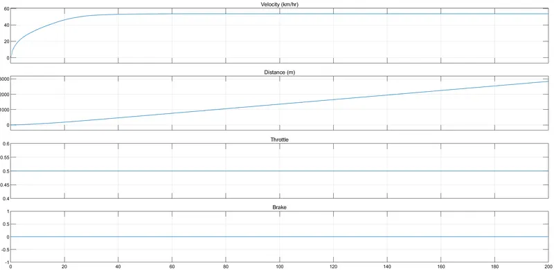
In this graph, the Throttle Value & Brake value remains constant at 0.5 & 0 respectively. During the initial stage the velocity of the vehicle increase rapidly, as the engine reaches its constant RPM the velocity becomes constant at 53.5 Km/h. As time increases the distance covered by the vehicle increases.
case 2: Baja AVT model with a dashboard
Input signals:
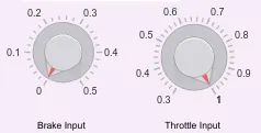
In this case, the Brake & Throttle input can be varied during the simulation. Here the knob block is used to change the Brake & Throttle inputs.
Signal builder block is used to create the input signals for the CVT ratio as shown below.
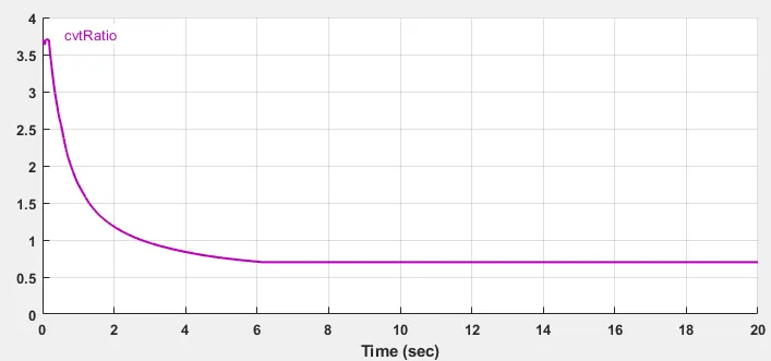
The CVT ratio decreases exponentially from around 3.6 at 0 sec to around 0.6 at 6 sec & remains constant.
m1 & m2 are used as the mass inputs for the ideal mechanical rotational inertia. The speedVector & torqueVector are used in Generic engine parameters. The torque vs speed curve is shown below.
Working principle:
The throttle input from the Knob block is passed to the engine. The engine output is connected to the RPM sensor, to collect the engine RPM data. Then it is connected to the CVT block. Here the CVT block has 2 inputs one from the engine & another from the signal builder CVT ratio. The variable gear ratio changes its gear ratio during the simulation as per the CVT ratio input. CVT block output is connected to the simple gear block. The output of the simple gear block is connected to the Vehicle body block, this block has another input from the Knob block brake input. Since the model considered is a two-wheel-drive vehicle, the input signal from the simple gear is connected to both rear wheels. Along with that, the Brake input is also connected to both rear wheels. And Vehicle body block provides the Velocity & distance as output. So after a simulation, the following results are obtained.
Result analysis:
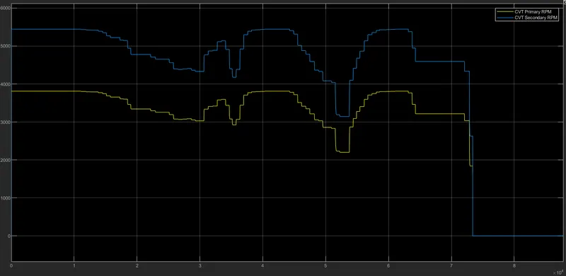
In this case, the Throttle input is at maximum position. so the initial velocity of the CVT primary shaft is 1750 RPM, as the throttle value varies the RPM increases to 3800. Due to the variable-ratio gear, the CVT secondary shaft reaches the velocity from 0-5400 RPM. As the Throttle varies the primary shaft & secondary shaft RPM varies accordingly.
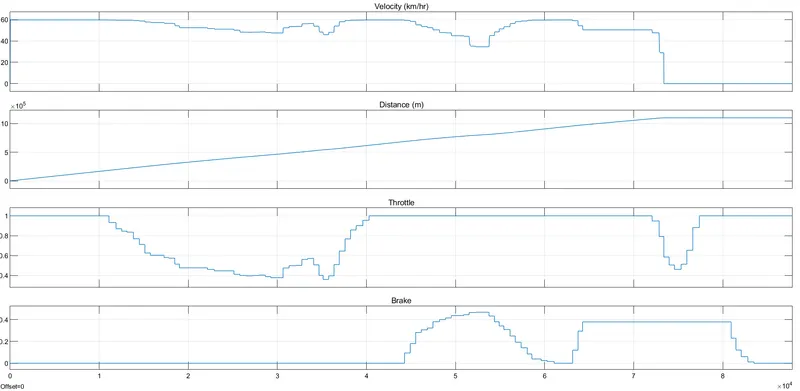
In this graph, during the initial time Throttle Value & Brake value are at 1 & 0 respectively. So the velocity of the vehicle increase rapidly, as the engine reaches its constant RPM the velocity becomes constant at around 60 Km/h. As time increases the distance covered by the vehicle increases. When the Throttle is decreased & brake has applied the velocity of the vehicle becomes 0 Km/h & the vehicle will stop moving. So the graph of the distance traveled by the vehicle remains constant at this point. If the brake value is more than the Throttle value the engine will turn off. So the velocity becomes 0 Km/h.
Case 3: Baja AVT lookup table model with a dashboard :
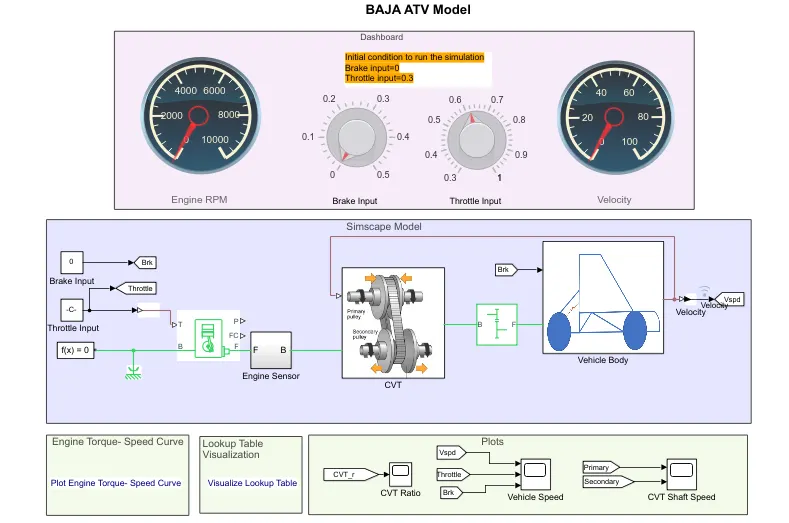
In the above 2 cases, we have seen that by giving some random values to the CVT ratio & checking the vehicle performance. It is not realistic, because the CVT ratio depends on the vehicle velocity. So in this case closed-loop model is created using the lookup table.
Input signals:
In this case, the Brake & Throttle input can be varied during the simulation. Here the knob block is used to change the Brake & Throttle inputs.
The below-mentioned graph data are used in the lookup table. The feedback signal is coming from the velocity to the CVT block.
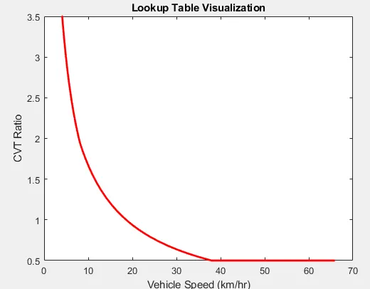
The CVT ratio decreases as the speed increases.
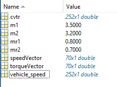
m1 & m2 are used as the mass inputs for the ideal mechanical rotational inertia. The speedVector & torqueVector are used in Generic engine parameters. The torque vs speed curve is shown below.
Working principle:
The throttle input from the Knob block is passed to the engine. The engine output is connected to the RPM sensor, to collect the engine RPM data. Then it is connected to the CVT block. Here the CVT block has 2 inputs one from the engine & another from the lookup table. The variable gear ratio changes its gear ratio during the simulation as per the CVT ratio input from the feedback loop. CVT block output is connected to the simple gear block. The output of the simple gear block is connected to the Vehicle body block, this block has another input from the Knob block brake input. Since the model considered is a two-wheel-drive vehicle, the input signal from the simple gear is connected to both rear wheels. Along with that, the Brake input is also connected to both rear wheels. And Vehicle body block provides the Velocity as output. So after a simulation, we got the following results.
Result analysis:
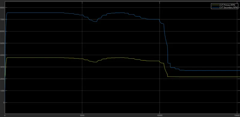
In this case, the Throttle input is at maximum position. so the initial velocity of the CVT primary shaft is 1750 RPM, as the throttle value varies the velocity increases to 3800 RPM. Due to the variable-ratio gear, the CVT secondary shaft reaches the velocity from 0-7570 RPM. As the Throttle varies the primary shaft & secondary shaft RPM varies accordingly.
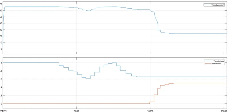
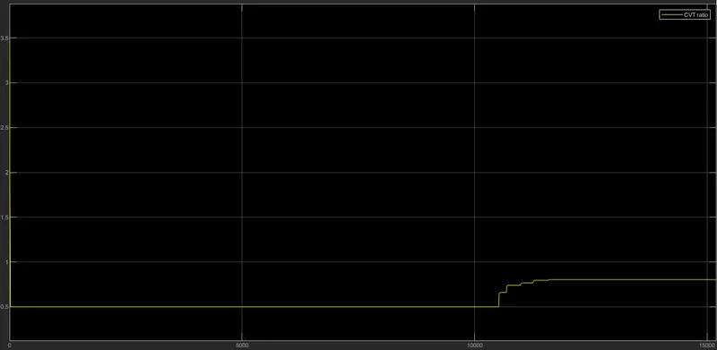
In this graph, during the initial time Throttle Value & Brake value are at 1 & 0 respectively. So the velocity of the vehicle increase rapidly, as the engine reaches its constant RPM the velocity becomes constant at around 65 Km/h. When the Throttle is decreased & brake has applied the velocity of the vehicle decreases. Similarly, the changes in the CVT ratio as brake applied can be observed.
Chapter-3
Conclusion:
By analyzing all the above cases it is observed that:
- The velocity of the vehicle increase as the throttle increases and decreases as the brake is applied.
- Maximum speed achieved by the vehicle.
- How the variable ratio gear Changes in open loop condtion(case 1 & 2) & close loop condtion(case 3).