Week-7 Challenge: DC Motor Control
1) Speed control of Dc motor using BJT H bridge :
The BJT when used for power switching application, behave as IGBT. When it is conducting (BJT in operating in saturation region), a forward voltage drop Vf is developed between collector and emitter(in the range of 1V). Therefore, the IGBT block can be used to model BJT.
The IGBT block does not simulate the gate current controlling the BJT or IGBT. The switch is operated by simulink signal (1/0). The Dc motor uses a preset model(5HP 240V 1750rpm). The mean armature voltage can be varied from 0 to 240 by varying the duty cycle from 0 to 100% specified in the pulse generator.
The below simulink model for control of dc motor using H bridge is shown:
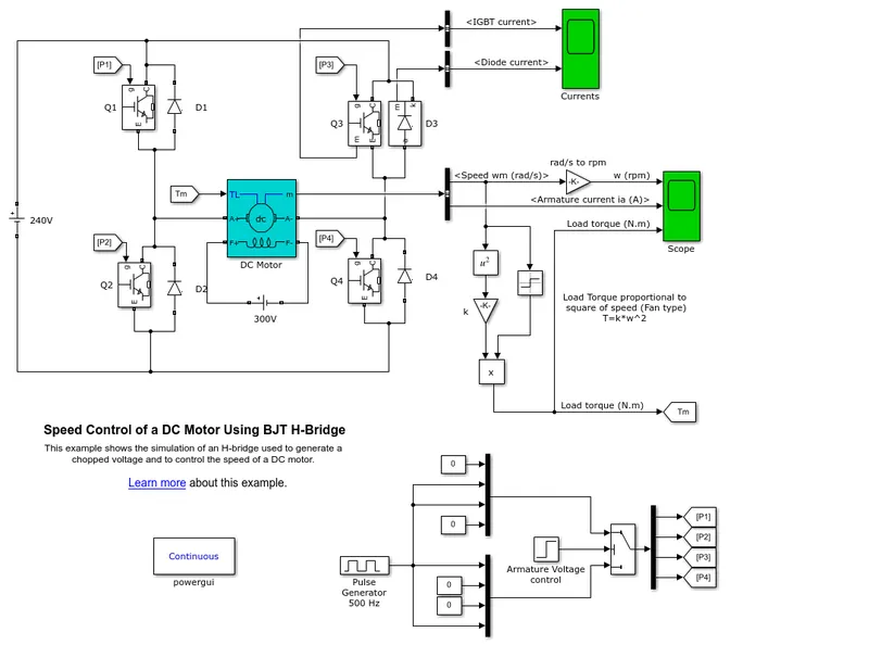
The H bridge consists of four BJT/diode pairs (BJT simulated by IGBT models). Two transistors are switched simultaneously Q1 and Q4 or Q2 and Q3. When Q1 and Q4 are fired, the positive voltage is applied to the motor and the diodes D2 and D3 operates as freewheeling diodes when Q1 and Q4 are switched off. When Q2 and Q3 are fired, a negative voltage is applied to the motor as a result of which, the motor runs in the opposite direction. And the diodes D1 and D4 operate as free wheeling diodes when Q2 and Q3 are switched OFF.
b) Below is the graph obtained for 75%duty cycle.
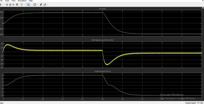
- It can be observed that the current is shooting up at the start and attains stability after certain period of time.
- The same thing happens when the voltage across the motor terminals is reversed(The current shoots up in the negative direction).
Let us now reduce the duty cycle to 50% and observe the scope results.
- The duty cycle can be adjusted in the pulse generator of the model.
Below is the scope results for 50% duty cycle.
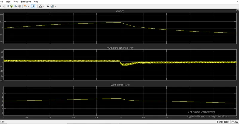
It can be observed that the current peak has reduced after reducing the duty cycle both in positive and negative direction.
c). The 200HP Dc motor is seperately excited with a constant 150V DC field voltage source. The armature voltage is provided by IGBT converter controlled by two PI regulators. The converter is fed through 515V DC bus obtained by rectification of a 380V AC 50hz voltage source. In order to limit the DC bus voltage during dynamic braking mode, a braking chopper is added between the diode rectifier and the DC7 block.
The first regulator is a speed regulator, followed by current regulator. The speed regulator outputs the armature current reference(in p.u) used by the current controller in order to obtain the electromagnetic torque needed to reach the desired speed. The speed reference change rate follows the acceleration and deceleration ramps in order to avoid sudden reference changes that could cause armature over current and de stabilize the system. The current regulator controls the armature current by computing the appropriate duty ratios of the 5 khz pulses of the four IGBT devices (Pulse width Modulation). For proper system behaviour, the instantaneous pulse values of IGBT devices 1 and 4 are opposite to those of IGBT devices 2 and 3. This generates the average armature voltage needed to obtain the desired armature current. In order to limit the amplitude of the current oscillations, a smooting inductance is placed in series with the armature circuit.
3) Type C Chopper drive:
This type of chopper can operate in first and second quadrant. In the first quadrant, the chopper drive operates the motor in forward motoring mode because both voltage and current are in first quadrant. Hence the power is positive.
Below circuit is a two quadrant chopper drive.
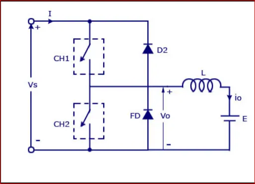
When the switch ch1 is closed, the supply voltage appears across the motor(whic is positive) the current completes its path through vh1, the inductor and then to the negative of source. when the switch ch2 is operated, the current freewheels through the diode D1 therefore we can see that the current direction reverses but voltage is positive, as a result of which, the motor operates in forward braking region as the power is negative.
Therefore we can conclude that the current in the two quadrant chopper can be either positive or negative but the voltage is always positive. (Note: the switches ch1 and ch2 should not be operated simultaneously as it would cause a short circuit across the source.)
Run the simulink model of two quadrant chopper drive and see the results of current and voltage.
https://drive.google.com/file/d/1pKB1Tr-ipJE5flme4vUQRUWX9XEgddS8/view?usp=sharing
When the
4) Brushless DC motor:
In the conventional DC motors, there will be friction between brushes and commutator as a result of which they gradually wear away. This problem with conventional DC motors has overcome by brushless dc motor (no brushes).
The rotor of BLDC motor is of permanent magnet. In order to make the rotor rotate, the current through the stator has to continuosly change in order to keep the rotor rotating hence the stator coil is fed through an inverter. The position of the rotor is sensed by the hall effect sensors and accordingly the stator coils are energised. This motor is also known as self synchronous motor.