Week-7 Challenge: DC Motor Control
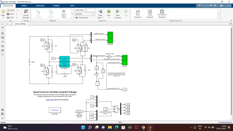
1A.To run and explain MATLAB demo model named"speed control of a dc motor using BJT H-bridge:
working:
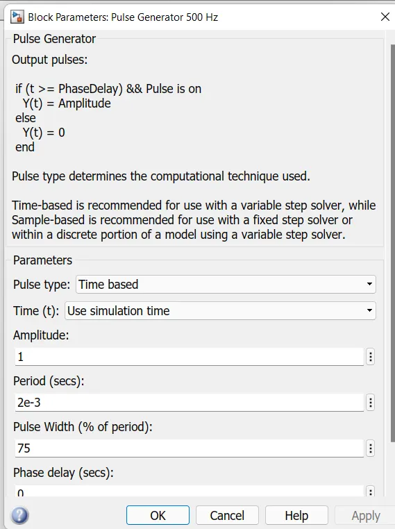
- in the above circuit the input voltage is generated from the plus generator where the amount of supply and duty cycle is assigned in the pulse generator.
- pulse width=ON+OFF
- duty cycle=ON/ON+OFF
- D=PW/T
- Then the switch block is connected to the pulse generator through armature voltage control block.
- the H-bridge consists of 4 BJT/diode pairs. Two transistors are switched simultaneoulsy:Q1 and Q4 or Q2 and Q3.
When Q1 and Q4 are fired, a positive voltage is applied to motor and diodes D2-D3 operates as free-wheeling diodes, when Q1 and Q4 are switched off.
when Q2 and Q3 are fired, a negative voltage is applied to motor and diodes D1-D4 operates as free-wheeling diodes, when Q2 and Q3 are switched off.
- A switch block at bottom of circuits splits the power supply into 4 parts namely they are[{p1}{p2}{p3}{p4}].these inputs are in goto from block.
- that block is used to send signal to"from block" that have the sspecified tag. if the tag visibility is"scoped", then a goto tag visibility block must be used to define the visibility of that particular tag. the block icon displays the selected tag name.
- therefore these 4 types of input are connected to transistor Q1,Q2,Q3 and Q4 through "from block";an"from block" recieves the signal from the"goto block" with the specified tag. the block icon displays the selected tag name.
- this formation is called an H-bridge, an H-bridge is an arrangement of transistor that allowa a circuits full control over a standard electric dc motor.
- the DC motor ids connected to battery and the mechanical input of DC motor is initiated as torque.
- load torque proportional to square of speed.
- T=k*w^2
where,
T=load torque
w=speed
torque for mechanical input of dc motor also switched by goto and from.the output of dc motor is connected with "bus sector" whereas the speed is plotted in the scope.a conversion of speed from rad/sec to rpm is held between the BUS sectors to scope using converter block.
1B.Comment on the armature current shoot-up from the scope results:
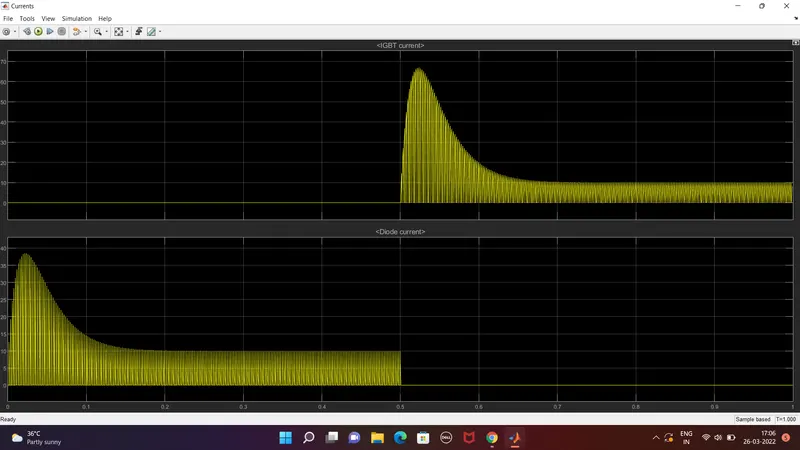
- In the current output the amount of circuit acted is shown asthe graphical representation during the period of duty cycle. the scope shows IGBT current and diode current passed in the quadrant Q3 and D3.
- where Q3 represent as IGBT current and D3 is represented as diode current in scope.
- the graph shows that when the switch Q3 is off on the starting stage of current flow and diode current is on that stage.
- during the 0.5 sec of time and D3 switch is ON that are given according to pulse generator and after the time period of 0.5 sec and D3 switch is OFF and IGBT current is acted after 0.5 sec and Q3 switch remains ON.
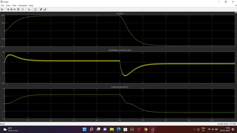
- The speed and armature current is obtained by the dc motor and load torque is calculated by load torque proportional to square of speed.
- In starting point, there is a sudden shootup is acted.
- In this scope shows that speed is increased in certain period of time and at that time armature current is positive whereas load torque also moves forward.
- After the time period of 0.5 sec which is given in pulse generator, sudden shoot-up is acted and speed gets decreased in that time armature current is in negative terminal whereas torque act as reverse action.
- here the sudden shoot up is acted while armature current is processed at a positive and negative terminal.
1C. DC7 - Four quadrant chopper 200 HP DC Drive:
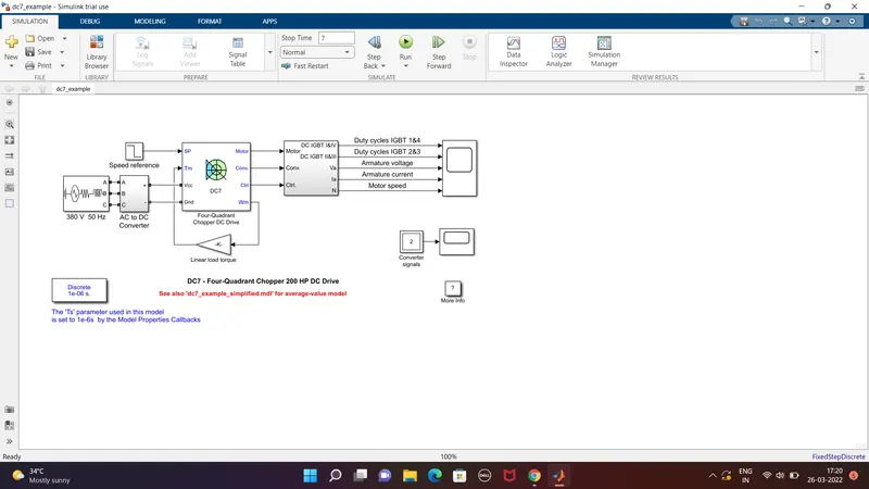
- The 200 HP DC motor is seperately excited with a constant 150 V DC field voltage source.
- the armature voltage is provided by an IGBT converter controlled by two PI regulators.
- the converter is fed by a 515 V DC bus obtained by rectification of a 380 V AC 50 Hz voltage source.
- In order to limit the DC bus voltage during dynamic braking mode, a braking chopper has been added between the diode rectifier and the DC7 block.
- The first regulator is a speed regulator, followed by a current regulatot. the speed regulator outputs the armature current reference used by the current controller in order to obtain the electromagnetic torque needed to reach the desired speed.
- the speed reference change rate follows acceleration and deceleration ramps in order to avoid sudden reference changes that could cause armature over-current and destabilize the system.
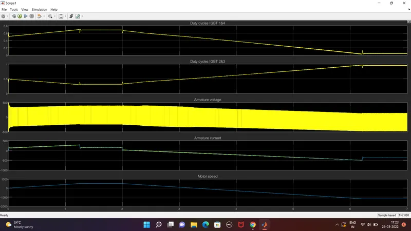
- the current regulatory controls the armature current by computing the appropriate duty ratios of the 5KHz pulses of the four IGBT devices.
- for proper system behavious, the instantaneous pulse values og IGBT devices 1 and 4 are opposite to those of IGBT devices 2 and 3.
- this generates the average armature voltage needed to obtain the desired armature current. in order to limit the amplitude of the current oscillations, a smoothing inductance is placed in series with the armature circuit.
OUTPUT:
| BJT H-BRIDGE DRIVER | FOUR QUADRANT CHOPPER DRIVE |
|
|
2. Simulink model for a 2 Quadrant chopper is:
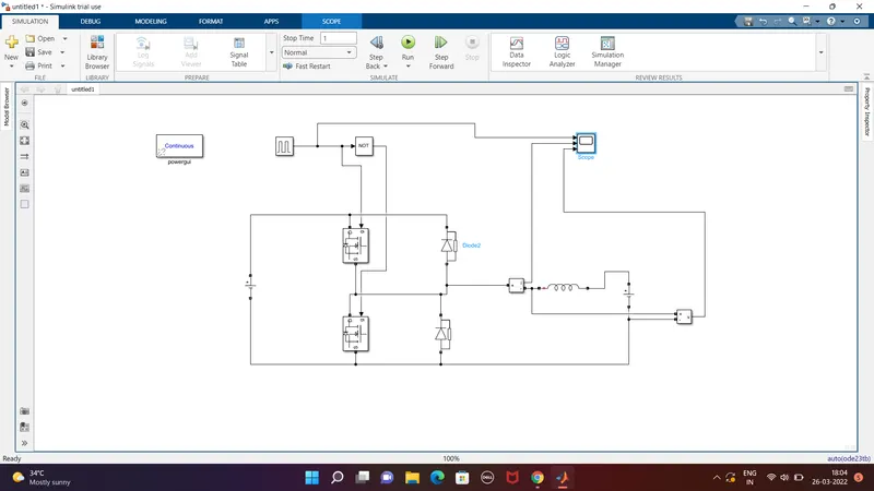
explanation for model construction:
- click on simulink browser and open the library to search for required components as POWERGUI,VOLTMETER,AMMETER,SOURCE,MOSFET,DIODE,PULSE GENERATOR,INDUCTOR,NOT OPERATOR to build C- class chopper.
- Arrange the blocks as per circuit connection shown above in model.
- Double click on MOSFET and DIODE block to disable the measurment port, and rotate the diode in upward direction as per our rquirement.
- Open series RLC band block and change the branch type to with default value 1mH , once done arrange according to circuit diagram.
- Open logical operator and select NOT in operation options, connect its input to output of pulse generator block. the reason we use NOT gate to ensure both the switches does not conduct simultaneously if they do so sopply will be short circuited.
- once done we will be measuring the voltage by connecting its first port at starting of inductor and other to DC2 splly which is connected adjacent.
- And output is connected to first and third port of scope input, current measurment port is also connected to second port of scope and third port is taken from output of pulse generator.
- double click on main DC voltage supply and set amplitude(v) to 24v and for adjacent DC2 supply set amplitude as 12v.
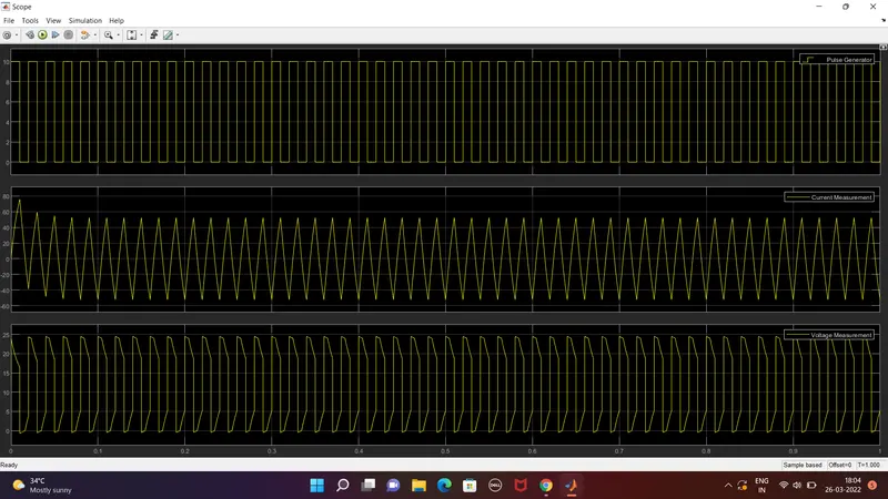
- open pulse generator block set amplitude to 10 for better viewing , time period set to 0.002 sec, pulse width is 50.
- now set the simulation time to 1 sec and run the simulation.
3.Introduction about brushless DC motor:
brushless DC motors or BLDC motors have become a significant contributor of the modern drive technology.their rapid grin popularity has seen an increasing range of applications in the fields of consumer appliances, automotive industry, industrial automation, chemical and medical, aerospace and instrumentation.
Even though they have been used for drives and power generation for a long time, the sub kilowatt range, which has been dominated by brushed DC motors, has always been a grey area. But the modern power electronics and microprocessor technology has allowed the small brushless dc motors to thrive, both in terms price and performance.
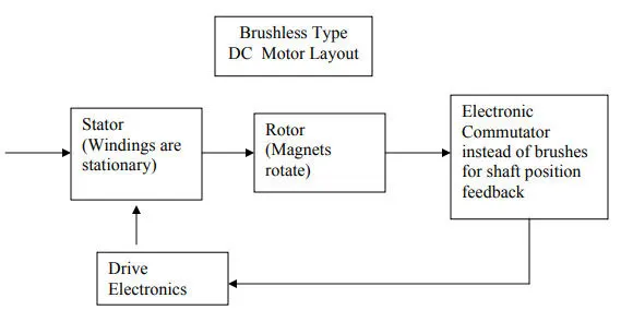
A Brushless DC motor is similar to a brushed DC motor but as the name suggests, a BLDC doesn't use brushes for commuatation but rather they are electronically commutated. In conventional brushed DC motors, the brushes are used tp transmit the power to the rotor as they turn in a fixed magnetic field.
As mentined earlier, a BLDC motor used electronic commutation and thus eliminates the mechanically torn brushes.
Construction of a BLDC motor:
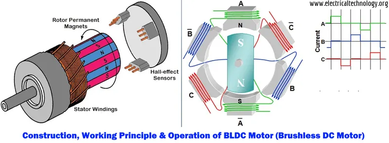
the main design difference between a brushed and brushless motors is the replacement of mechanical commutator with an electric switch circuit. keeping that in mind, a BLDC motor is type of synchronous motor in the sense that the magnetic field generated by the stator and the rotor revolve at the same frequency.
nrushless motors are available in three configurations:single phase, two phase and three phase. out of these, the three phase BLDC is the most commonly used.
STATOR:
the structure of the stator BLDC motor is similar to that of an induction motor. it is made up of stacked steel laminations with axially cut slots for winding. the winding in BLDC are slightly different than that of the traditional induction motor. generrally, mostly BLDC motor consists of three stator windings that are connected in a star 'Y' fashion. additionally, based on the coil interconnections, the stator windings are further divided into trapezoidal and sinusoidal motors..
ROTOR:
th rotor part of the BLDC motor is made up of permanent magnets .based on the application, the number of poles can vary between two and eight with north(N) and south(S) poles placed alternately.the following image shows three different arrangements of the pols. in the first case, the magnets are placed on the outer periphery of the rotor.
WORKING PRINCIPLE:
Consider the following setup of three windings in the stator designated A,B and C. For the sake of understanding, let us replace the rotor with a single magnet.
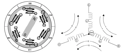
we know that when a current is applied through a coil, a magnetic field is generated and the orientation of the field lines i.e., the poles of the generated magnet will depend on the direction of the current flowing through the coil.
using the principle, if we supply current to the coil A sothat it will generate a magnetic field and attract the rotor magnet. the position of the rotor magnet will shift slightly clockwise and will align with A.if we now pass current through coils B and C one after other, the rotor magnet will rotate in clock wise direction.
to increase efficiency, we can wind the opposite coils using a single coil so that we get double attraction. further increasing the efficiency, we can energize two coils at the same time so that one coil will attract the magnet and the other coil will repel it.during this time, the third will be idle.
for a complete 360 degrees rotation of the rotor magnet, six possible combinations of the coils, A,B and C are applicable
ADVANTAGES OF BRUSHLESS DC MOTOR:
since BLDC motors are electronically commutated, there are several advantages over traditional brushed DC motors.some of them are:
- no wear and tear(due to absence of brushes)
- high efficiency
- better speed vs torque characterstics
- long life
- less noise or noiseless operation
- significantly higher rpm