Week-7 Challenge: DC Motor Control
1) A)
Aim:
To explain a MATLAB demo model named ‘Speed control of a DC motor using BJT H-bridge’.
Explaination:
Duty cycle:
- PWM simulates different voltage outputs via a repeating series of pulses.
- These pulses occur at a steady rate, but the length of each pulse varies depending on the simulated voltage.
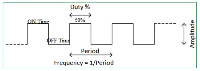
- The time period T consists of Ton and Toff time period.
T=Ton+Toff
- Frequency is inversely proportional to time period (f=1/T).
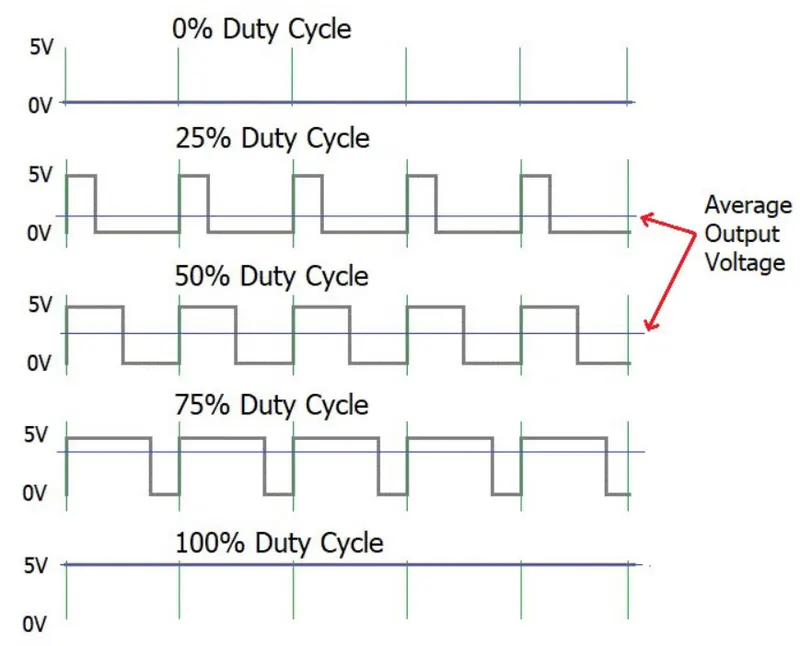
- By varying the duty ratio value we obtain various voltage i.e switching the devices on and off according to its switching frequency.
- These pulse signals are given to the switches such as MOSFET ,IGBT or BJT to control the speed of motor.
IGBT:
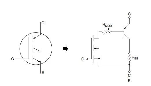
- IGBTs are the device of choice for high-voltage (400–1200 V) and medium- to high current (10–1000 A) automotive power switching applications because of their superior current conduction capability over high-voltage power MOSFETs.
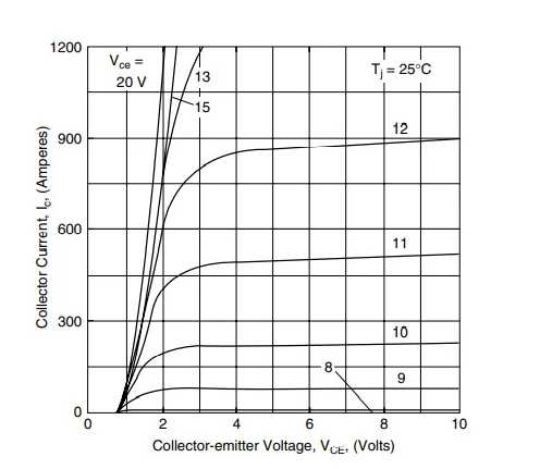
- 600–900 V IGBT inverter power modules are exclusively used in electric and hybrid propulsion systems with a power rating greater than 20 kW.
- 400–600 V discrete IGBTs are also widely used as the ignition coil driver in conventional vehicles powered by internal combustion engines.
- The IGBT is a switching transistor controlled by voltage applied to the gate terminal.
- Device operation and structure are similar to that of a power MOSFET.
- The principal difference is that the IGBT relies on conductivity modulation to reduce on-state conduction losses.
- The IGBT has high input impedance and fast turn-on speed like a MOSFET, but exhibits an on-state voltage drop and current-carrying capability comparable to that of a bipolar transistor while switching much faster.
Diodes:
- Diodes are the simplest semiconductor device, comprising of a PN or Schottky junction with two external terminals.
- Diodes are used in applications that require current to flow in one direction only.
- Rectify AC current from the alternator to DC current that charges the battery.
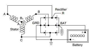
- Allow load current freewheeling as the anti-parallel diodes for IGBTs or MOSFETs in inverter or converter applications.
- A freewheeling diode provides an alternative path for the inductive load current when the main IGBT or MOSFET turns off, and prevents high Ldi/dt voltage spikes from damaging the main switching devices.
- Suppress voltage transients when being reverse biased (Zener diodes).
Speed control of a DC motor using BJT H-bridge:
- The Bipolar Junction Transistor (BJT) when used for power switching applications, operates as an IGBT.
- When it is conducting (BJT operating in the saturated region), a forward voltage Vf is developed between collector and emitter (in the range of 1 V).
- Therefore, the IGBT block can be used to model the BJT device.
- The IGBT block does not simulate the gate current controlling the BJT or IGBT.
- The switch is controlled by a Simulink® signal (1/0).
- The DC motor uses the preset model (5 HP 24V 1750 rpm).
- It simulates a fan type load (where Load torque is proportional to square of speed).
- The armature mean voltage can be varied from 0 to 240 V when the duty cycle (specified in the Pulse Generator block) is varied from 0 to 100%.
- The H-bridge consists of four BJT/Diode pairs (BJT simulated by IGBT models).
- Two transistors are switched simultaneously: Q1 and Q4 or Q2 and Q3.
- When Q1 and Q4 are fired, a positive voltage is applied to the motor and diodes D2-D3 operate as free-wheeling diodes when Q1 and Q4 are switched off.
- When Q2 and Q3 are fired, a negative voltage is applied to the motor and diodes D1-D4 operate as free-wheeling diodes when Q2 and Q3 are switched off.
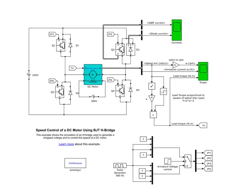
- The above block model represents the 'Speed Control of a DC Motor Using BJT H-Bridge'.
- The supply voltage of 240 V is given to the circuit.
- Two IGBT and diode switches are placed in both the side A and B.
- The DC motor is connected with the switches to form H shape due to which it is called as H bridge circuit.
- Above circuit is functioned in such a way that the switches in side A or B are not operated simulaneously.
Input parameters:
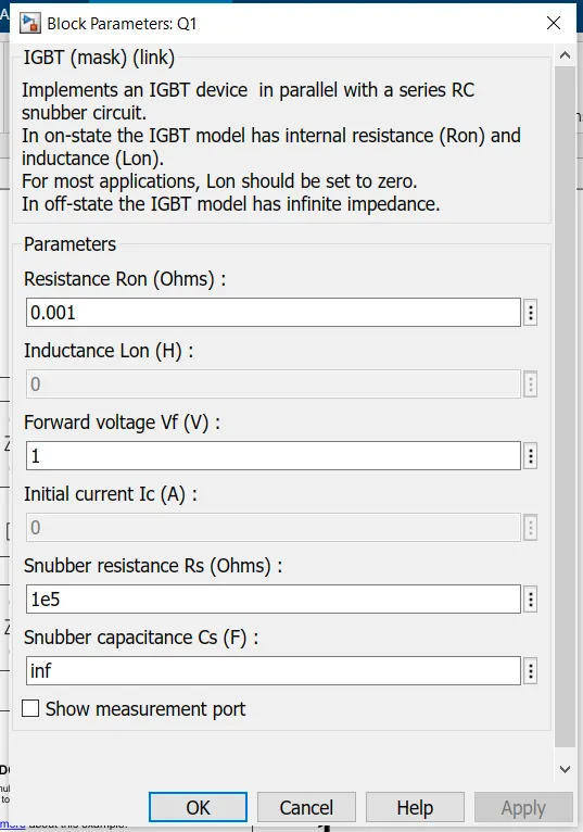
- The input resistance of 0.001 ohms is given.
- 1v forward voltage and 1e5 snubber resistance is given to the device.
- The aboves values is maintained in all IGBT devices.
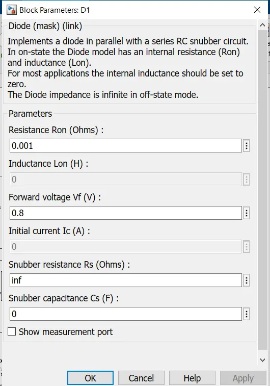
- 0.8V forward voltage and 0.001 ohms of internal resistance is given to the diode devices.
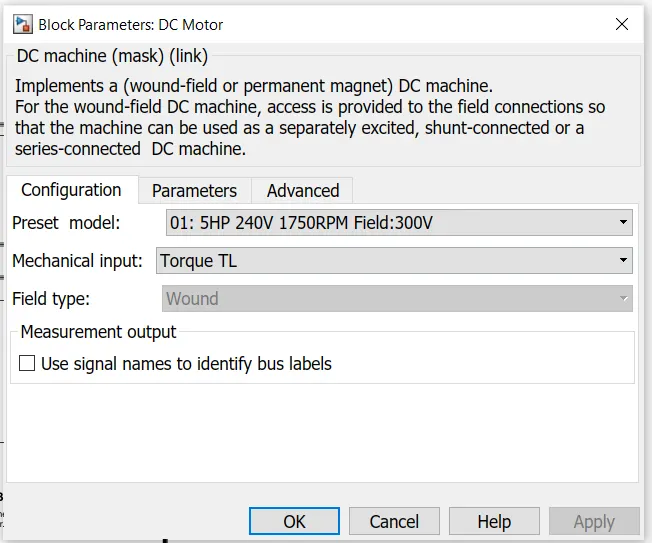
- The motor with 5HP power, 240 V , 1750 rpm speed and with field voltage of 300V is used.
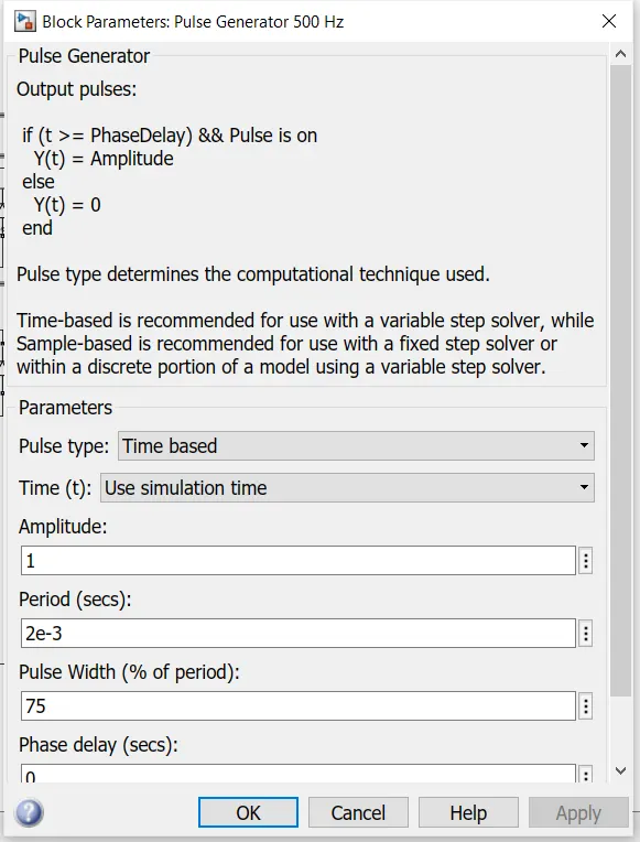
- The pulse is given through the pulse generator to the IGBT to control the speed of motor.
- In this model 75 % of duty cycle is given to the circuit.
- 1 amptitude is maintained in the circuit for a time period of 2e-3 seconds.
Operation:
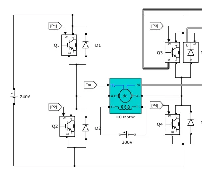
- The 240 V is given as the input supply to the circuit.
- The switches are arranged as shown in the diagram.
- The seperate 300V supply voltage is given to the dc motor.
- The P1,P2,P3 and P4 are the input generated pulse signal given the IGBT devices.
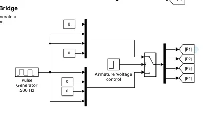
- This is the block in which the pulse is generated by varying the duty cycle.
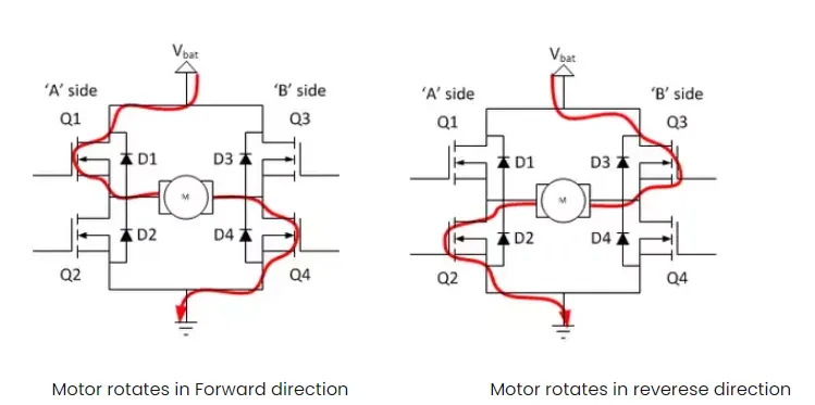
- From the above diagram it is clear that during the conduction of switch Q1 and Q4 the motor operates in forward direction and Q3 and Q4 in reverse direction respectively.
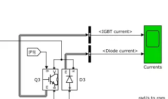
- The output of the devices viewed through the scope by connecting the output current of IGBT and diode.
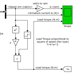
- The speed obtained is converted into rpm by multiplying with 30/pi.
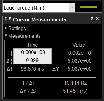
- 6.062e-4 gain is multip,es to the speed of the motor inorder to obtain the load torque.
- These values are again fed back to the motor.
1)B)
Aim:
To comment on the armature current shoot-up from the scope results.
Explaination:
- When Q1 and Q4 are fired, a positive voltage is applied to the motor and diodes D2-D3 operate as free-wheeling diodes when Q1 and Q4 are switched off.
- When Q2 and Q3 are fired, a negative voltage is applied to the motor and diodes D1-D4 operate as free-wheeling diodes when Q2 and Q3 are switched off.
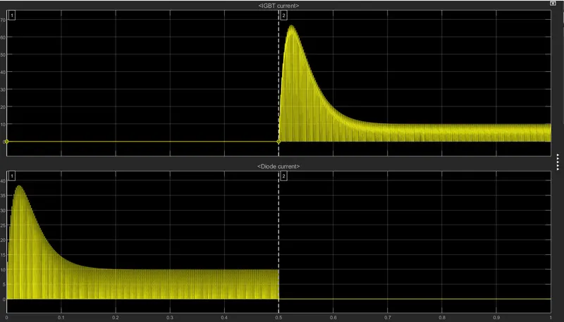
- This the output of the IGBT and diode current.
- From this it is clear that when the IGBT is On then the diode is Off.
Phase 1:
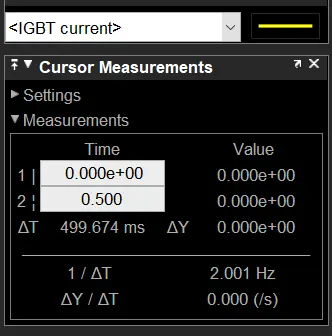
- The value of IGBT is zero i.e off state.
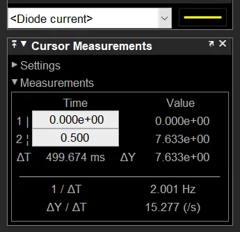
- The diode is in conduction mode.
Phase 2:
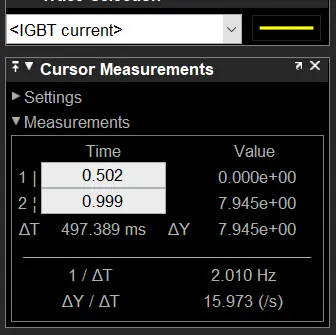
- IGBT is in conduction mode.
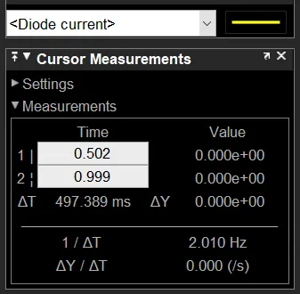
- Diode is in off condition.
- The value of the motor speed is converted from rad/s into rpm by multiplying with 30/pi to obtain value of speed.
- The load torque is calculated by T=k*w^2 .
- Where the k represents the motor constant and it is multipled with the square of speed.
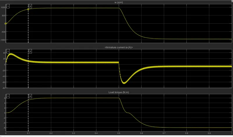
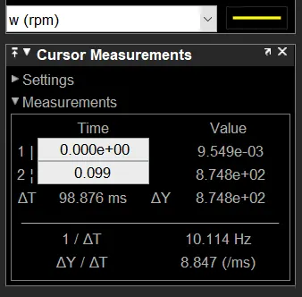
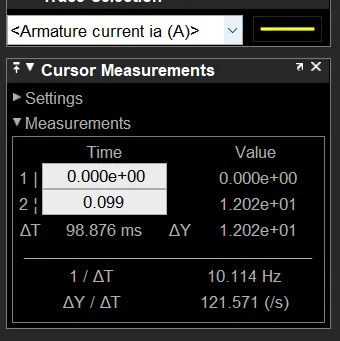
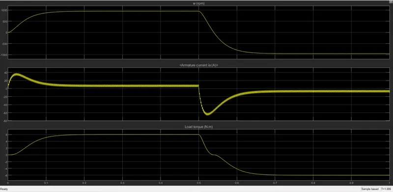
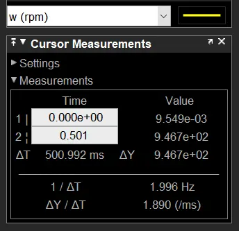
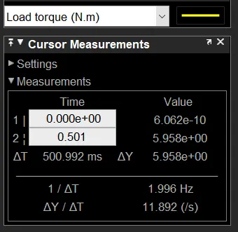
- It is observed that when the motor is operated with the duty cycle ratio of 75 percent , the speed of the motor increases gradually.
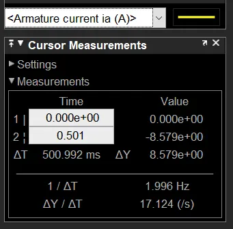
- But the armature current of the dc motor is high while starting the motor and decreases.
- Similar to the speed the load torque increases.
DC motor operating in forward direction:
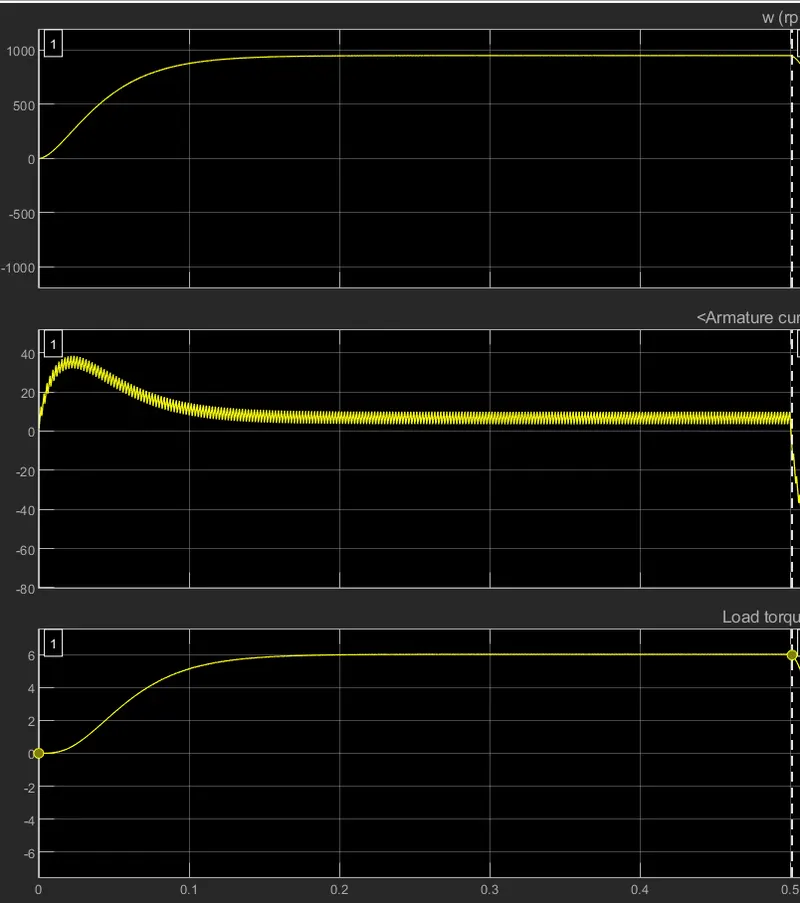
- When the motor is operated in forward direction then the following speed, armature current and the load torque is obtained.
DC motor operating in reverse mode:
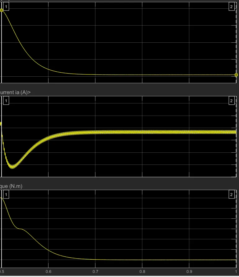
- When the dc motor operates in reverse mode then the above graph is obtained.
- It is found that the speed , armature current and the load torque occurs in negative cycle with the values shown below.
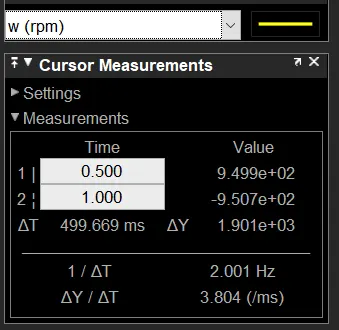
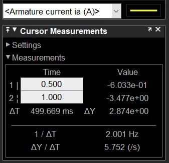
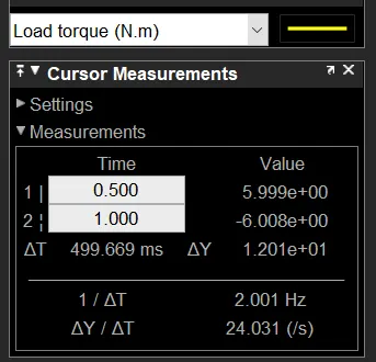
Duty cycle :45%
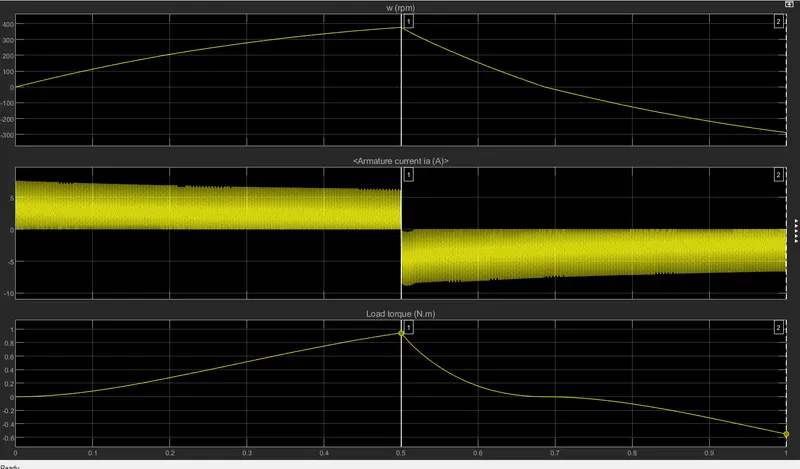
- The above graph represents the speed , armature current and torque.
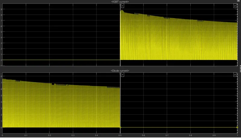
- IGBT and diode current graph is shown above.
Duty cycle 75% and 45%:
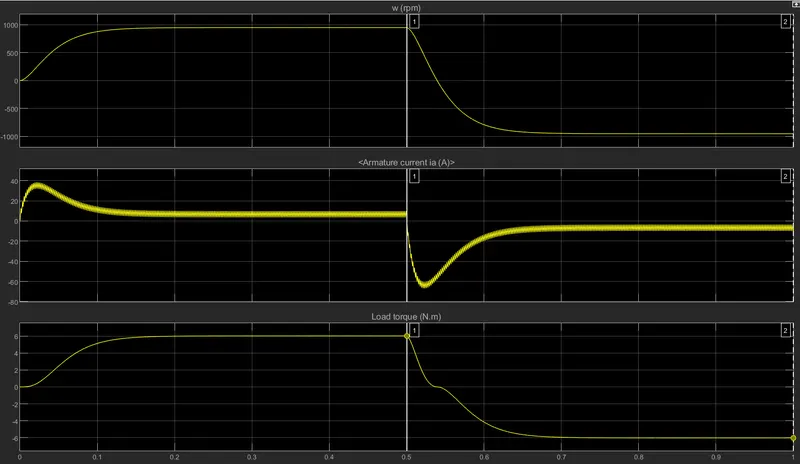
- From the above graph it is clear that by varying the duty cycle the motor speed is varied.
- As the duty cycle increases, the speed of the motor also increases rapidly.
1)C)
Aim:
To refer ‘The Four-Quadrant Chopper DC Drive (DC7) block’and to compare it with the H-bridge model.
Principle:

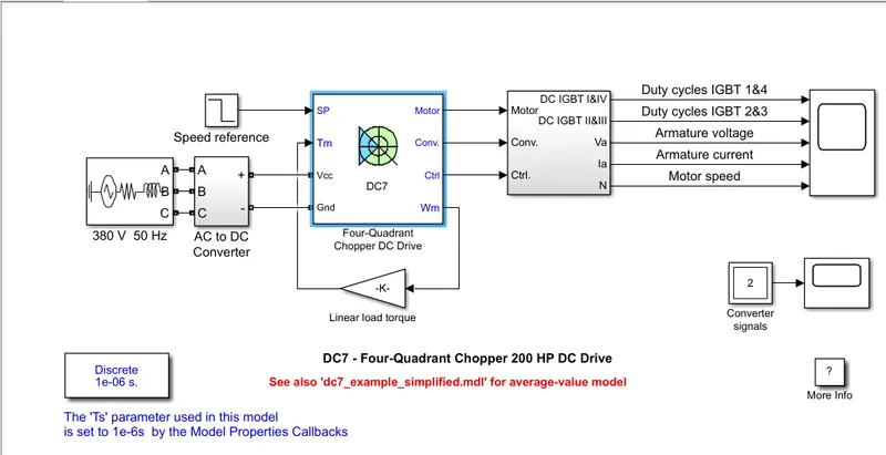
- The Four-Quadrant Chopper DC Drive (DC7) block represents a four-quadrant, DC-supplied, chopper (or DC-DC PWM converter) drive for DC motors.
- This drive features closed-loop speed control with four-quadrant operation.
- The speed control loop outputs the reference armature current of the machine.
- Using a PI current controller, the chopper duty cycle corresponding to the commanded armature current is derived.
- This duty cycle is then compared with a sawtooth carrier signal to obtain the required PWM signals for the chopper.
- The main advantage of this drive, compared with other DC drives, is that it can operate in all four quadrants (forward motoring, reverse regeneration, reverse motoring, and forward regeneration).
- In addition, due to the use of high switching frequency DC-DC converters, a lower armature current ripple (compared with thyristor-based DC drives) is obtained.
- However, four switching devices are required, which increases the complexity of the drive system.
- The Three-Phase Source block implements a balanced three-phase voltage source with an internal R-L impedance.
- The three voltage sources are connected in Y with a neutral connection that can be internally grounded or made accessible.
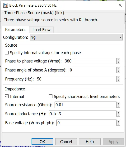
- We can specify the source internal resistance and inductance either directly by entering R and L values or indirectly by specifying the source inductive short-circuit level and X/R ratio.
- 380V of phase to phase voltage is given with 50 Hz frequency.
- R=0.01 ohms and L=0.1e-3 henry is given as input.
- It is connected to AC to DC rectifier.
- The rectifier bridge is connected to the braking chopper with the following inputs as shown below.
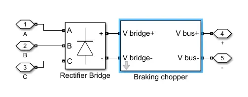
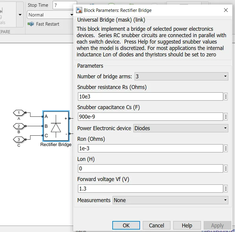
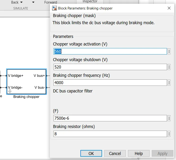
- The output obtained from the rectifier is DC which is connected to the four quadrant chopper.
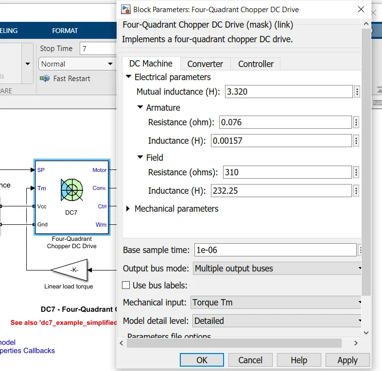
- The Vcc and Gnd terminals are connected to the rectifier output port .
DC machine:
- Mutual inductance: 3.320 H
- Armature resistance:0.076 ohms
- Armature inductance:0.00157 H
- Field resistance: 310 ohms
- Field inductance:232.25 H
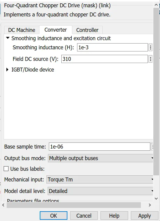
Converter:
- Smoothing inductance:1e-3
- Field DC source: 310 V
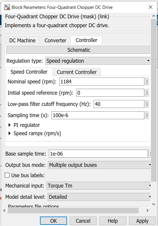
Controller:
- Speed: 1184 rpm
- Low pass filter cut off frequency:40 Hz
- Sampling time:100e-6
Reference speed:
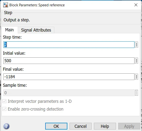
- Step time:2 sec
- Initial value: 500
- Final value:1184
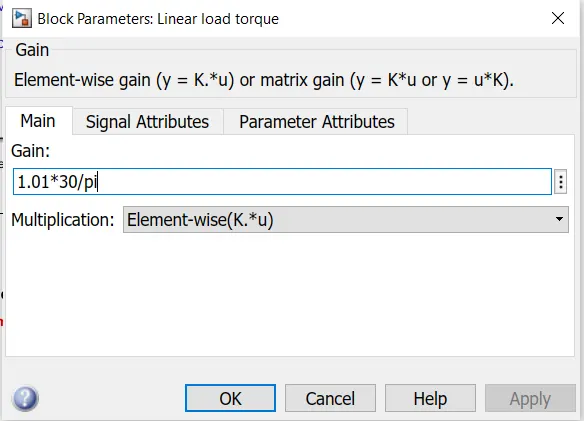
- The obtained speed is converted into rpm and fed back to the mechanical input load torque Tm.
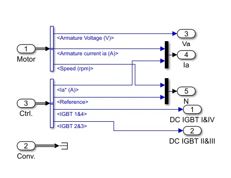
- The values of armature voltage, armature current, speed and operation of power IGBT devices are connected to the outport and scope to view the results.
Output:
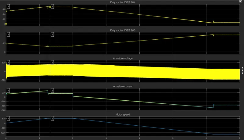
- The operations performed by the circuit are forward motoring, reverse regeneration, reverse motoring, and forward regeneration.
- Graph 1:Dutycycle of IGBT 1 and 4 , the motor rotates in forward direction.
- The obtained duty cycle is more than 50%
- Graph 2:Dutycycle of IGBT 2 and 3, the motor rotates in reverse direction.
- The obtained duty cycle is less than 50%.
- Graph 3:Armature voltage, we can see the variation in the voltage from 500 V to -500V.
- Graph 4:Armature current, there is a sudden increase in the current during forward motoring operations and sudden decrease in the current negatively during the reverse operations of the motor.
- Graph 5:Motor speed varying from 0 to 500 rpm speed and suddenly decreasing due to reverse operations.
Converter signals:
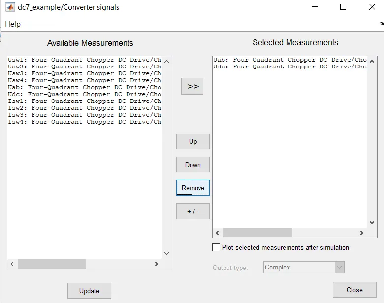
- The required measurements can be choosen from the available signals module and the output can be viewed.
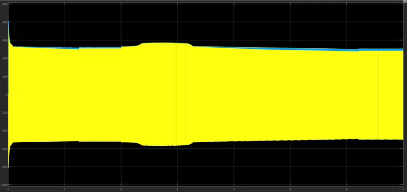
- This is the ouput obtained in the converter signal Uab and Udc inputs.
Comparision of Speed control of a DC motor using BJT H-bridge vs The Four-Quadrant Chopper DC Drive (DC7) block:
| Speed control of a DC motor using BJT H-bridge | The Four-Quadrant Chopper DC Drive (DC7) block |
|
|
|
|
|
|
|
|
|
|
|
|
2)
Aim:
To develop a 2-quadrant chopper using simulink & explain the working of the same with the relevant results.
Principle:
- A chopper is basically a dc to dc converter whose main function/usage is to create adjustable dc voltage from fixed dc voltage sources through the use of semiconductors.
Type -C chopper or Two-quadrant type-A Chopper:
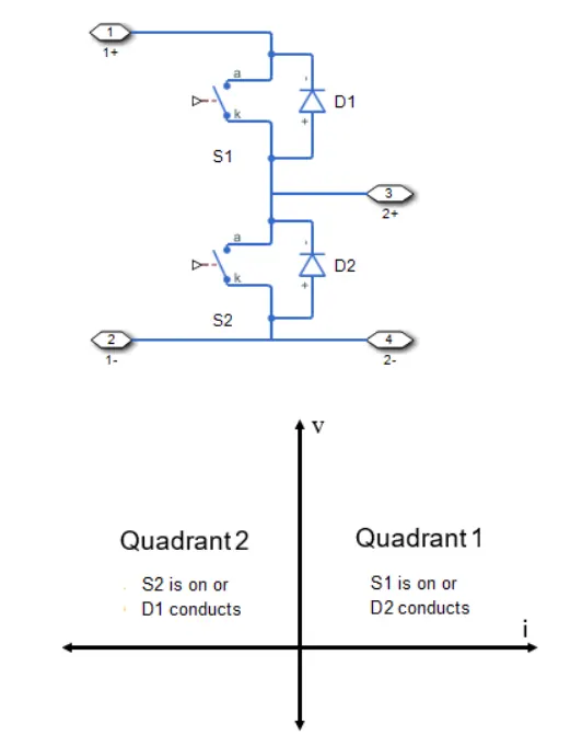
- Type C chopper is obtained by connecting type –A and type –B choppers in parallel.
- We will always get a positive output voltage V0 as the freewheeling diode FD is present across the load.
- When the chopper is on the freewheeling diode starts conducting and the output voltage v0 will be equal to Vs .
- The direction of the load current i0 will be reversed.
- The current i0 will be flowing towards the source and it will be positive regardless the chopper is on or the FD conducts.
- The load current will be negative if the chopper is or the diode D2 conducts.
- We can say the chopper and FD operate together as type-A chopper in first quadrant.
- In the second quadrant, the chopper and D2 will operate together as type –B chopper.
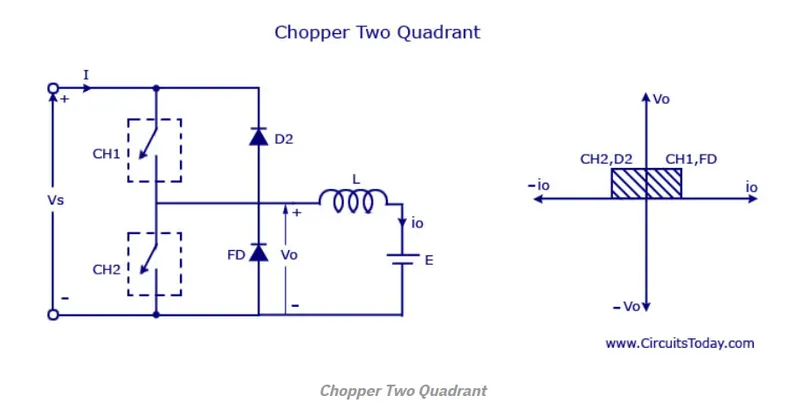
- The average voltage will be always positive but the average load current might be positive or negative.
- The power flow may be life the first quadrant operation ie from source to load or from load to source like the second quadrant operation.
- The two choppers should not be turned on simultaneously as the combined action my cause a short circuit in supply lines.
- For regenerative braking and motoring these type of chopper configuration is used.
Type D Chopper or Two-Quadrant Type –B Chopper:
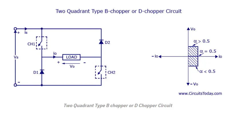
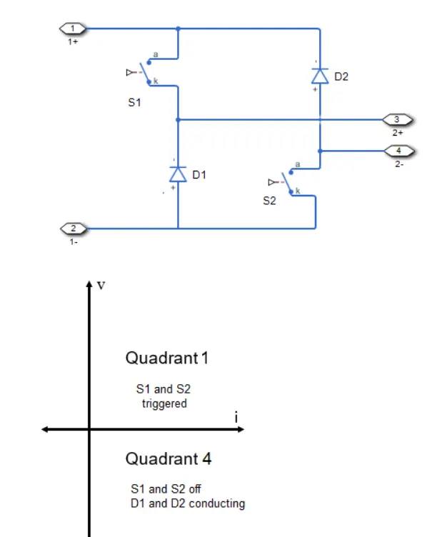
- The circuit diagram of the type D chopper is shown in the above figure.
- When the two choppers are on the output voltage v0 will be equal to Vs .
- When v0 = – Vs the two choppers will be off but both the diodes D1 and D2 will start conducting.
- V0 the average output voltage will be positive when the choppers turn-on the time Ton will be more than the turn off time Toff its shown in the wave form below.
- As the diodes and choppers conduct current only in one direction the direction of load current will be always positive.
- The power flows from source to load as the average values of both v0 and i0 is positive.
- From the wave form it is seen that the average value of V0 is positive thus the forth quadrant operation of type D chopper is obtained.
- From the wave forms the Average value of output voltage is given by
V0= (Vs Ton-VsToff)/T = Vs.(Ton-Toff)/T
Simulation:
Type -C chopper or Two-quadrant type-A Chopper:
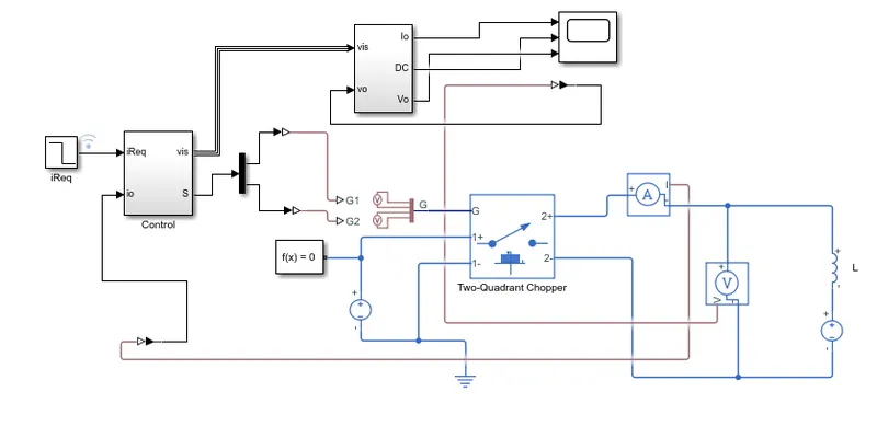
- The Step block provides a step between two definable levels at a specified time.
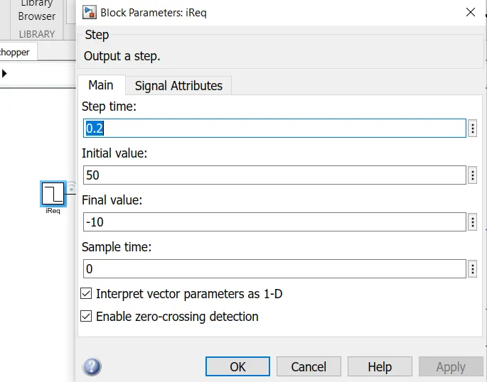
- 0.2 sec step time with 50 as initial value is given as input.
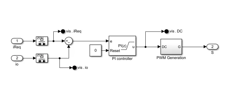
- The Rate Transition block transfers data from the output of a block operating at one rate to the input of a block operating at a different rate.
- The step input value is given to the inport 1 rate transistion block with sampling time 0.001 sec.
- The inport 2 contains the data from current sensor.
- Using summing block both the obtained values are given to the PI controller.
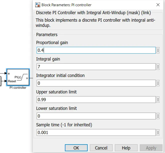
- From PI controller with proportional gain 0.4 and gain interval 7 of the signal is given to the pulse with modulation generator.
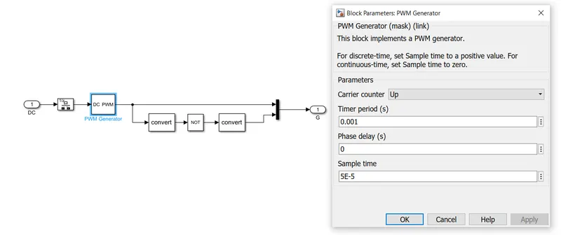
- Hence the obtained pulse is given to the semiconductor module of two quadrant chopper.
Two quadrant chopper:
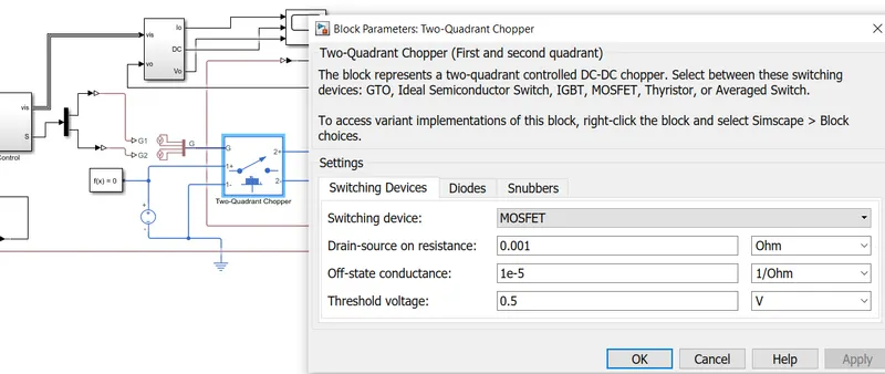
- The two quadrant chopper inbuilt switch is available in the semiconductor library.
- The MOSFET switch is choosen with the parameters shown above.
- 15 V power supply is given to the chopper circuit through the voltage source.
- The current sensor is connected in series and the voltage sensor in parallel.
- The inductance load with value of E as 5V is given in load side.
Output:
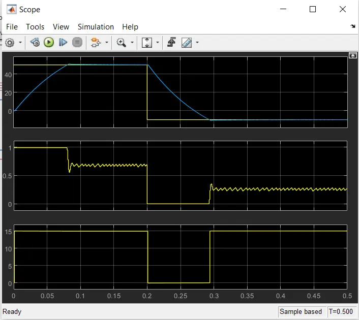
- The above image represents the output of the two quadrant chopper.
- Graph 1 represents the output current: We can find both positive and negative current as it is two quadrant operation of I and II.
- Graph 2 represents the duty cycle : We can find the switching of the MOSFET.
- Graph 3 represents the output voltage: The voltage is positive in this two quadrant operation.
Type D Chopper or Two-Quadrant Type –B Chopper:
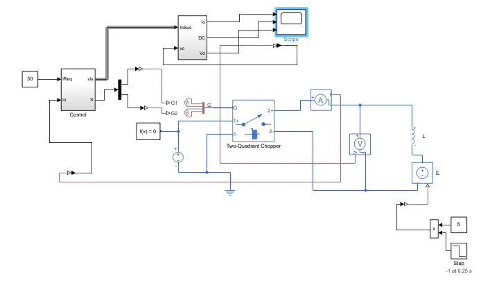
- The same procedure followed for type C chopper shall be followed.
- The input constant value 30 is given.
- The gate pulse is given to the MOSFET device.
- For two quadrant type D chopper the Model configuration is changed by Right clicking-Simscape-Model change -First and fourth quadrant operation.
- The voltage sensor is connected parallel and the current sensor in series.
- In the load side the the inductance and voltage source with step input is given.
- The output is viewed through the scope.
Output:
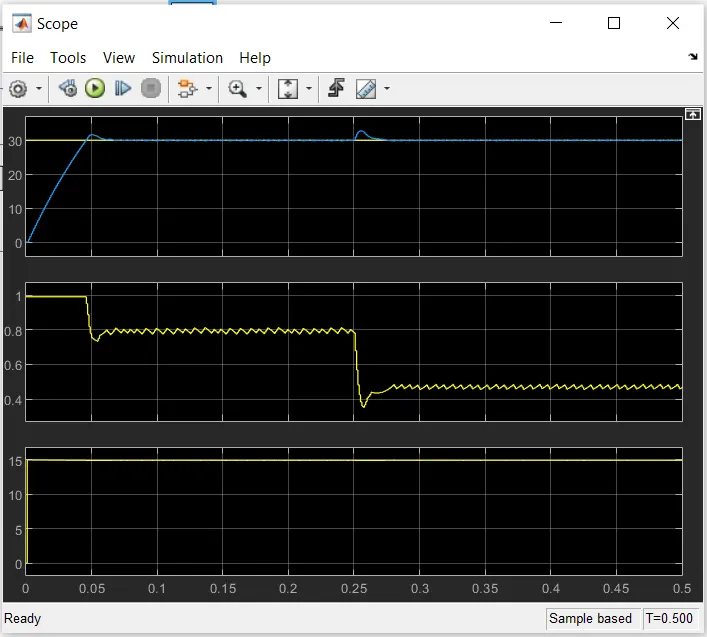
- The output of the current ,voltage and duty cycle is shown in the above image.
Result:
The 2-quadrant chopper using simulink is developed and explained with the relevant results.
3)
Aim:
To explain in a brief about operation of BLDC motor.
Explaination:
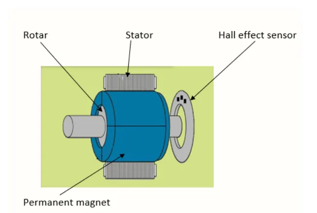
- A brushless DC motor is a rotating self-synchronous machine with a permanent magnet rotor and with known rotor shaft positions for electronic commutation.
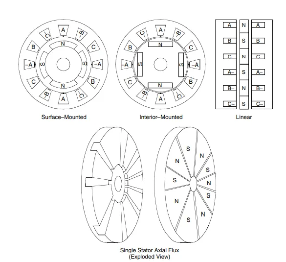
- Several types of electrical machines and drives have been referred to as BLDC,
including:
1. Permanent magnet synchronous machines (PMSMs)
2. BLDC trapezoidal back-electromotive force (back-EMF) surface-mounted magnet machines,
3. BLDC sinusoidal back-EMF surface-mounted magnet machines
4. BLDC interior-magnet machines
5. The BLDC motor and drive combination
6. Axial-flux BLDC
Construction:
- In this motor, the permanent magnets attach to the rotor.
- The current-carrying conductors or armature windings are located on the stator.
- They use electrical commutation to convert electrical energy into mechanical energy.
- The main design difference between a brushed and brushless motors is the replacement of mechanical commutator with an electric switch circuit.
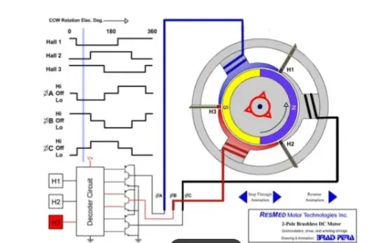
- A BLDC Motor is a type of synchronous motor in the sense that the magnetic field generated by the stator and the rotor revolve at the same frequency.
- Brushless motor does not have any current carrying commutators.
- The field inside a brushless motor is switched through an amplifier which is triggered by the commutating device like an optical encoder.
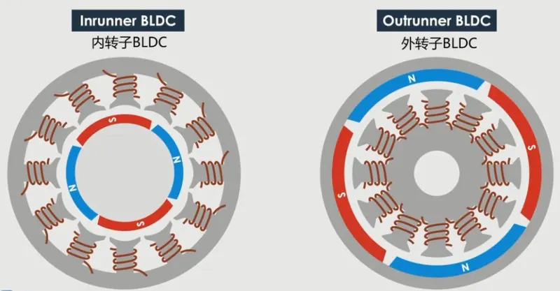
- The layout of a DC brushless motor can vary depending on whether it is in out runner style or inrunner style.
- Outrunner:The field magnet is a drum rotor which rotates around the stator. This style is preferred for applications that require high torque and where high rpm is not a requirement.
- Inrunner:The stator is a fixed drum in which the field magnet rotates. This motor is known for producing less torque than the out runner style but is capable of spinning at very high rpm.
- BLDC motor works on the principle similar to that of a brushed DC motor.
- The Lorentz force law which states that whenever a current carrying conductor placed in a magnetic field it experiences a force.
- As a consequence of reaction force, the magnet will experience an equal and opposite force.
- In the BLDC motor, the current carrying conductor is stationary and the permanent magnet is moving.
- When the stator coils get a supply from source, it becomes electromagnet and starts producing the uniform field in the air gap.
- Though the source of supply is DC, switching makes to generate an AC voltage waveform with trapezoidal shape.
- Due to the force of interaction between electromagnet stator and permanent magnet rotor, the rotor continues to rotate.
- With the switching of windings as High and Low signals, corresponding winding energized as North and South poles.
- The permanent magnet rotor with North and South poles align with stator poles which causes the motor to rotate.
Operations:
- The following setup of three windings in the stator designated A, B and C.
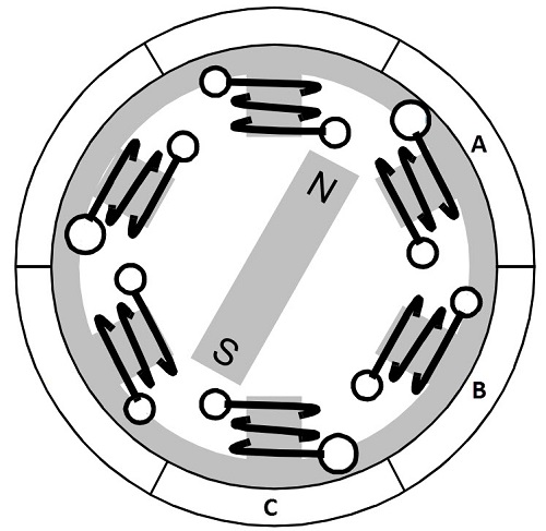
- We know that when a current is applied through a coil, a magnetic field is created and the poles of the generated magnet will depend on the direction of the current flowing through the coil.
- Using this principle, if we supply current to the coil A so that it will generate a magnetic field and attract the rotor magnet.
- The position of the rotor magnet will shift slightly clockwise and will align with A.
- If we now pass current through coils B and C one after the other then the rotor magnet will rotate in clock wise direction.
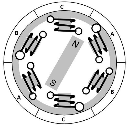
- To increase efficiency, we can wind the opposite coils using a single coil so that we get double attraction.
- Further increasing the efficiency, we can energize two coils at the same time so that one coil will attract the magnet and the other coil will repel it.
- During this time, the third will be idle.
- For a complete 3600 rotation of the rotor magnet, six possible combinations of the coils A, B and C are applicable and are shown in the following timing diagram.
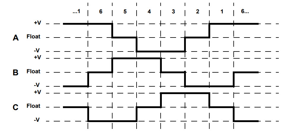
- Base on the above diagram, we can confirm that at any time, one phase is positive, one phase is negative and the third phase is idle.
- So, based on the inputs from the Hall Sensors, we have two switch the phases as per the above diagram.
Driving Brushless DC Motors
- If stator and rotor are essential parts of a BLDC Motor that are integral to it, then the driving electronics are equally essential.
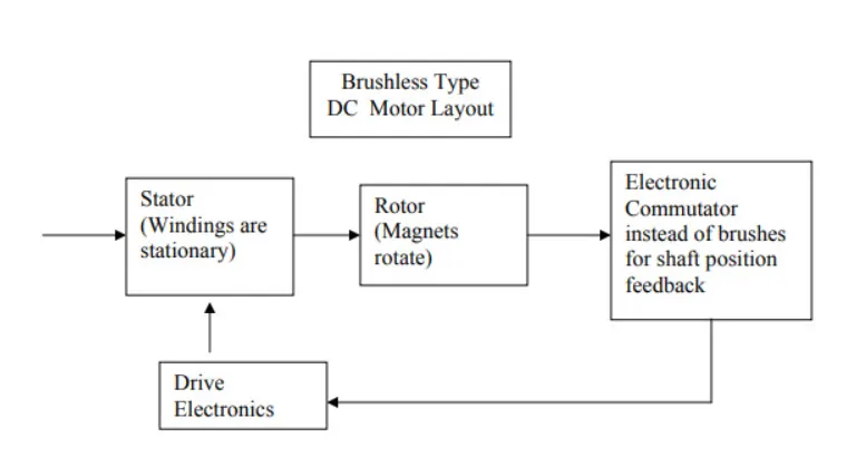
- Block diagram of a typical Brushless DC Motor control or drive system is shown in the following image.
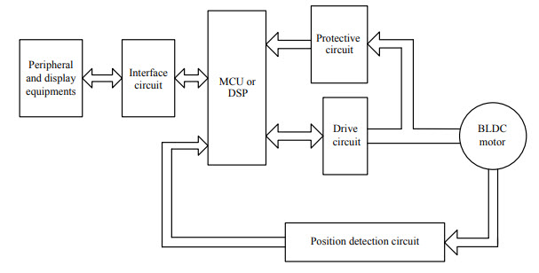
- This drive circuitry is often known as Electronic Speed Controller System or simply an ESC.
- One common setup is called the Full Bridge Drive Circuit.
- It consists of an MCU with PWM outputs, six MOSFETs for the three phases of the stator windings, feedback from the Hall sensors and some power supply related components.
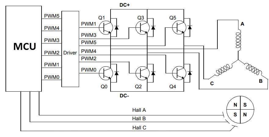
- The MCU can be programmed to appropriately switch the MOSFETS based on the data from the Hall Sensors.
Advantages:
- Less overall maintenance due to absence of brushes.
- Reduced size with far superior thermal characteristics.
- Higher speed range and lower electric noise generation.
- It has no mechanical commutator and associated problems.
- High efficiency and high output power to size ratio due to the use of permanent magnet rotor.
- High speed of operation even in loaded and unloaded conditions due to the absence of brushes that limits the speed.
- Smaller motor geometry and lighter in weight than both brushed type DC and induction AC motors.
- Long life as no inspection and maintenance is required for commutator system.
- Higher dynamic response due to low inertia and carrying windings in the stato.r
- Less electromagnetic interference.
- Low noise due to absence of brushes.
Limitations:
- These motors are costly.
- Electronic controller required control this motor is expensive.
- Requires complex drive circuitry.
- Need of additional sensors.
Applications:
- Computer hard drives and DVD/CD players.
- Electric vehicles, hybrid vehicles, and electric bicycles.
- Industrial robots, CNC machine tools, and simple belt driven systems.
- Washing machines, compressors and dryers.
- Fans, pumps and blowers.
Attachments:
https://drive.google.com/file/d/1jadgcHNarz3UDxqNT694HT3NwWF3V180/view?usp=sharing