Project
Modeling of an Continuously Variable Transmission System (CVT) BAJA All-Terrain Vehicle
Aim:
- To carry out the system-level simulation of the Continuously Variable Transmission System (CVT) BAJA All -Terrain Vehicle.
Objective:
- To write a detailed report on the simulation models of the Continuously Variable Transmission System (CVT) BAJA All-Terrain Vehicle.
- To analyze that while changing the throttle or brake input there is a change in the velocity and speed (RPM) of the vehicle engine.
Principle:
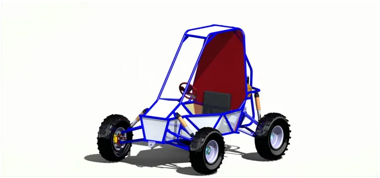
- An all terrain vehicle is also known as light utility vehicle.
- It is a vehicle that travels on low pressure tires, with a seat that is straddled by the operator, along with handle bar for steering control.
- It is designed to handle a wider variety of terrain than most other vehicle.
Components:
Vehicle body :
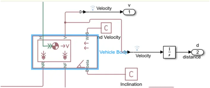
- Represents a two-axle vehicle body in longitudinal motion.
- The vehicle can have the same or a different number of wheels on each axle.
- The vehicle does not move vertically relative to the ground.
- Connection H is the mechanical translational conserving port associated with the horizontal motion of the vehicle body.
- Connections V, NF, and NR are physical signal output ports for vehicle velocity and front and rear normal wheel forces, respectively.
- Connections W and beta are physical signal input ports corresponding to headwind speed and road inclination angle.
Input Block Parameters:
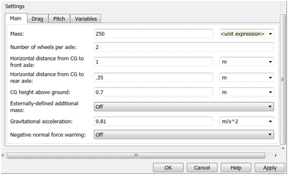
- The above image has the main setting values of the vehicle body.
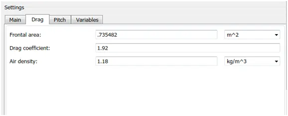
Drag specifications:
CVT :

- It consist of primary pulley, secondary pulley, variator and belt.
- The variator of the primary pulley moves outwards and the secondary pulley moves inwards such that the radius of the secondary pulley will be more than the radius of the primary pulley. Thus leading to speed reduction.
- Similarly when the variator of the primary pulley moves inwards and the secondary pulley moves outwards then it leads to over drive.
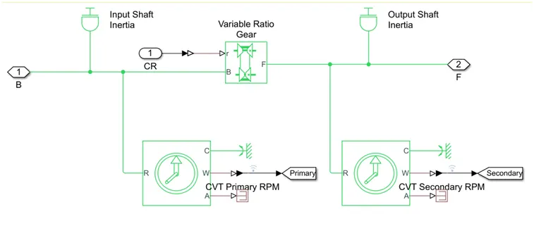
Variable Ratio Transmission:
- Represents a variable ratio gearbox such as implemented by mechanical belt CVT, electric or hydraulic transmissions.
- The physical signal input r defines the ratio of input to output angular shaft velocities.
- Connections B (base) and F (follower) are mechanical rotational conserving ports..
Inertia:
- The block represents an ideal mechanical rotational inertia.
- The block has one or two mechanical rotational conserving ports.
- The difference is purely graphical, as the ports are rigidly linked.
- The block positive direction is from its port to the reference point.
- This means that the inertia torque is positive if the inertia is accelerated in the positive direction.
Ideal Rotational Motion Sensor:
- This block measures angular velocity or angle in a mechanical rotational network.
- The sensor is ideal since it does not account for inertia, friction, delays, energy consumption.
- The physical signal ports W and A report the angular velocity and angle, respectively, of port R relative to port C.
- The measured angular velocity is positive when the angular velocity at port R is greater than the angular velocity at port C.
Engine:
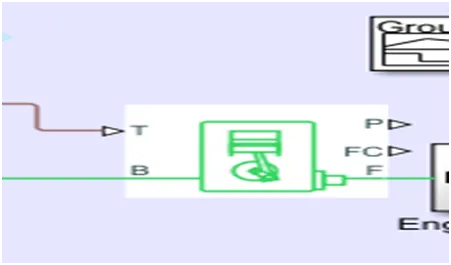
- Represents a system-level model of spark-ignition and diesel engines suitable for use at initial stages of modeling when only the basic parameters are available. Optional idle speed and red line controllers are included.
- The throttle input signal T lies between zero and one and specifies the torque demanded from the engine as a fraction of the maximum possible torque.
- If the engine speed falls below the Stall speed, the engine torque is blended to zero.
- If the engine speed exceeds the Maximum speed, the simulation stops and issues an error message.
- Connections F and B are mechanical rotational conserving ports associated with the engine crankshaft and engine block.
- Connections P and FC are physical signal output ports through which engine power and fuel consumption rate are reported.
Tire:
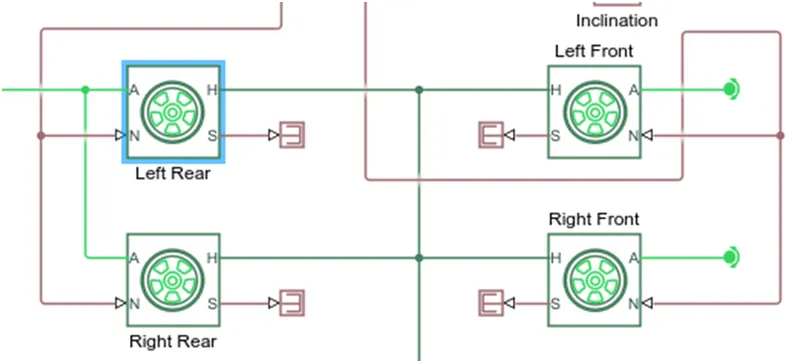
- Represents the longitudinal behavior of a highway tire characterized by the tire Magic Formula.
- The block is built from Tire-Road Interaction (Magic Formula) and Simscape Foundation Library Wheel and Axle blocks.
- Connection A is the mechanical rotational conserving port for the wheel axle.
- Connection H is the mechanical translational conserving port for the wheel hub through which the thrust developed by the tire is applied to the vehicle.
- Connection N is a physical signal input port that applies the normal force acting on the tire.
- The force is considered positive if it acts downwards.
- Connection S is a physical signal output port that reports the tire slip.
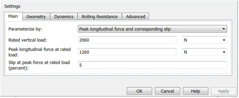
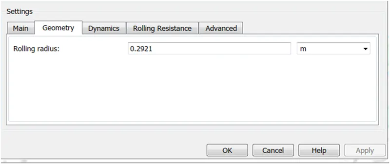
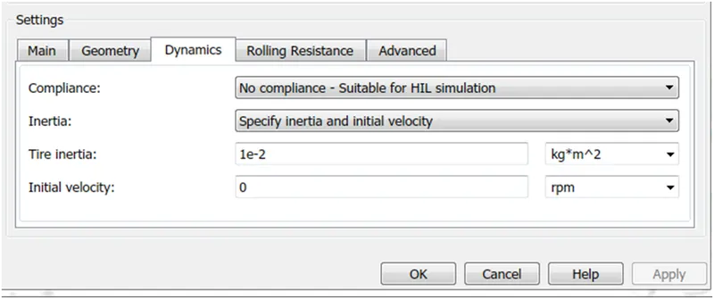
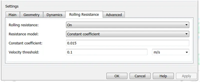
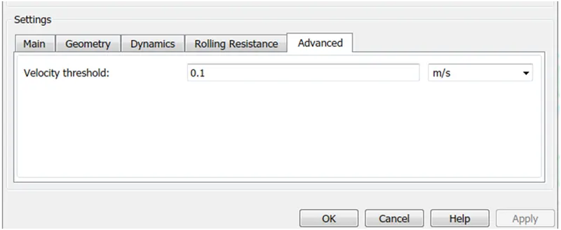
Input Block Parameters:
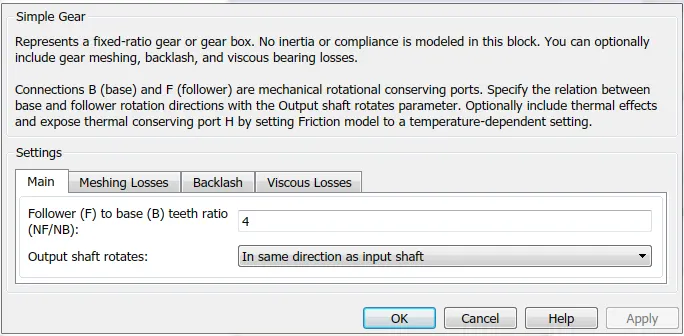
Simple Gear Ratio:
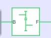
- To connect Engine and CVT we need a speed reduction block, so a simple gear block is connected across it.
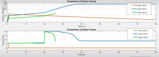
- For gear ratio 8 the simulation stops at 26 seconds.
- Maximum rpm is 3840.
- Gear ratio 4 is giving the desired vehicle velocity than gear ratio 2.
- So we consider value 4 as the gear ratio input.
Simulation Without Dashboard:
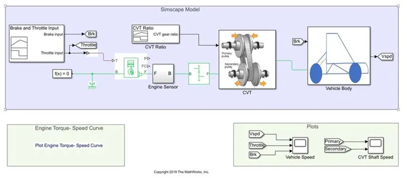
- The above model represents the BAJA ATV Model.
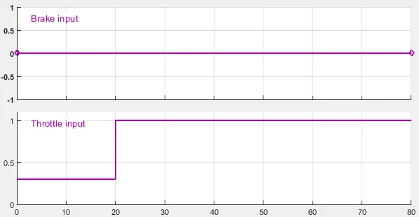
- The brake input and the throttle input are given to the simulation model through the Signal Builder block.
- Brake input is kept zero and the throttle input as 0.3 for the first 20 seconds and later it is made into 1.
- Then the output of the Signal Builder block is connected to the Generic Engine.
- The speed vector and the torque vector values of the Generic Engine can be extracted from the image.
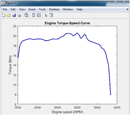
- The data points are extracted using GRABIT file exchanger and fed into the Generic Engine.
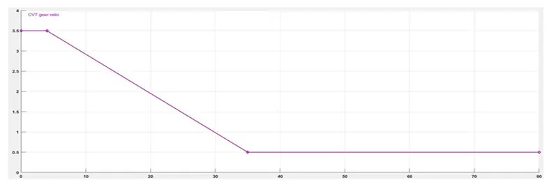
- The below image shows the input signal of CVT gear ratio through Signal Builder block.
Output:
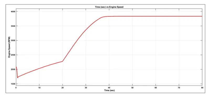
- The output of the AVT model without dash board is obtained.
- As the given throttle input varies the velocity increases.
- The velocity increases when the throttle value increases after 20 seconds.
Simulation With Dashboard:
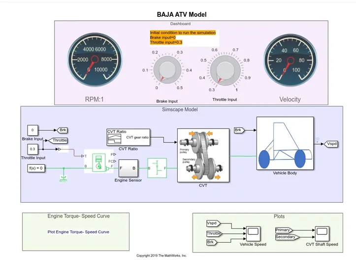
- Above same procedure is followed for the simulation with dashboard.
- But the brake and throttle input is given using the dashboard connected.
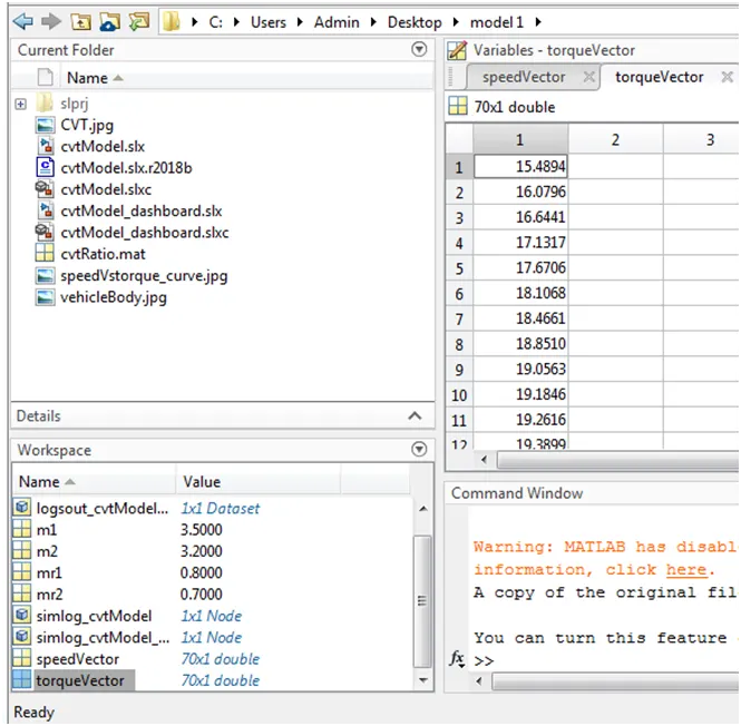
- CVT gear ratio is fed into the CVT block using the speed and torque vector data in the workspace.
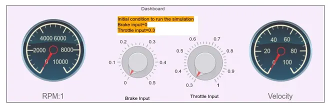
- The above dashboard represents Zero when the simulation is in OFF mode.
- By adjusting the input throttle knob the output vehicle velocity is obtained.
Output:
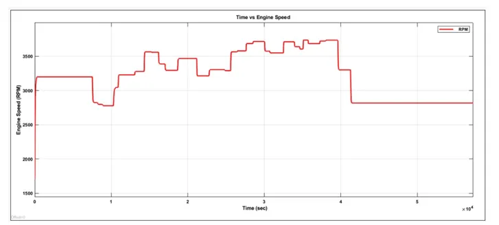
- The above is the output obtained by varying the throttle knob to 0.3 and brake input to zero.
Simulation With Dashboard Using Lookup Table:
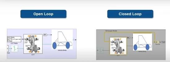
- Open loop: By giving random values of CVT we analyse the performance of vehicle.
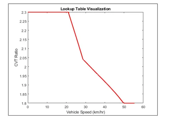
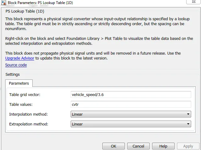
- Closed loop: As the CVT ratio depends upon the vehicle velocity it is given through lookup table as a closed loop.
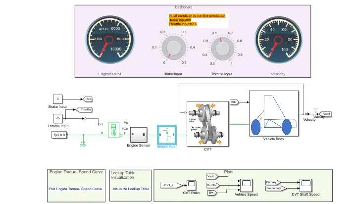
- The above simulaton represents the simulation with dashboard using lookup table.
- The vehicle speed and the cvtr are fed into the workspace as shown in the below image.
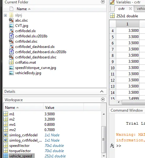
- The values of variables fed are shown below.
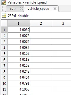
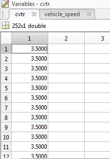
- Using the previous open loop model the script is written to lock the CVT values and the velocity .
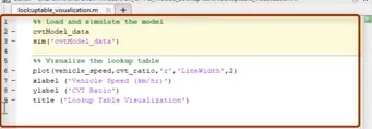
- The below lookup table is obtained.
- The feedback is obtained from the velocity to the CVT block.
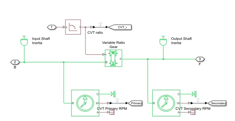
- Inside the CVT block we can find that the CVT ratio is fed to the variable ratio gear using lookup table.
Output:
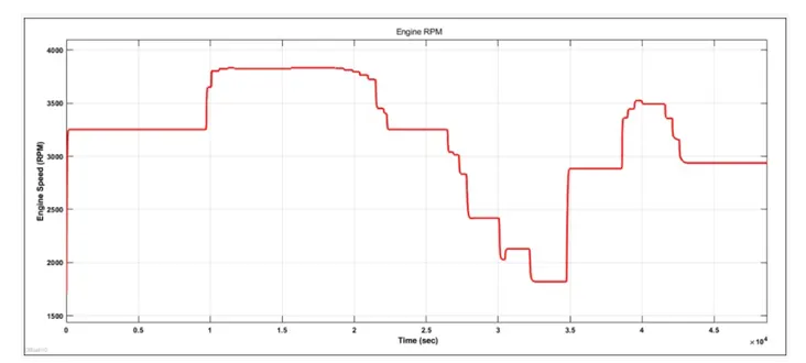
- By varying the input throttle knob the output vehicle velocity changes and the CVT ratio of both the primary and the secondary pulley changes accordingly.
Result:
- A detailed report on the simulation models of the Continuously Variable Transmission System (CVT) BAJA All-Terrain Vehicle is done.
- While changing the throttle or brake input there is a change in the velocity and speed (RPM) of the vehicle engine for the following models: i)simulation without dashboard ii) simulation with dashboard iii) simulation with dashboard using lookup table.