Week - 4
1) Control Logic Of A Washing Machine Using Stateflow
Aim:
To implement control logic of a washing machine using Stateflow.
Objective:
To obtain control logic of a washing machine using stateflow as follows:
1) system gets activated when the power supply is ON.
2) to stop the process when the water supply is OFF.
3) to allocate time of 200 seconds for soaking, 100 seconds for washing , 20 seconds for rinsing and 50 seconds for dryer runs.
Principle:
1)State flow is a control logic tool used to model reactive systems via state machines and flow charts wthin a Simulink model.
2)Simscape is used to create models of physical systems within the simulink.
3)In a washing machine the following are the process:
Soaking
Washing
Rinsing
Drying
Filling water
4)The above process are designed using the chart block and the output are viewed y connecting the lamp.
Simulation:
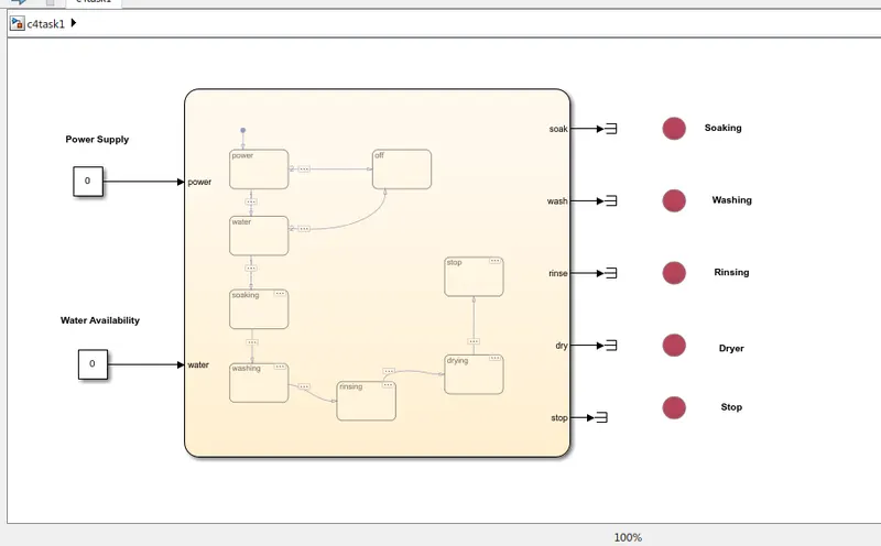
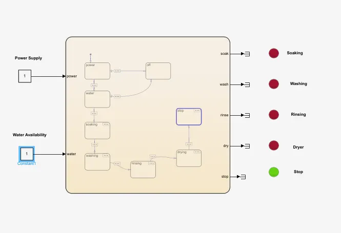
1) In the above simulation both the power and water supply present in the system is 0 , so the washing machine is in off state.
Inputs:
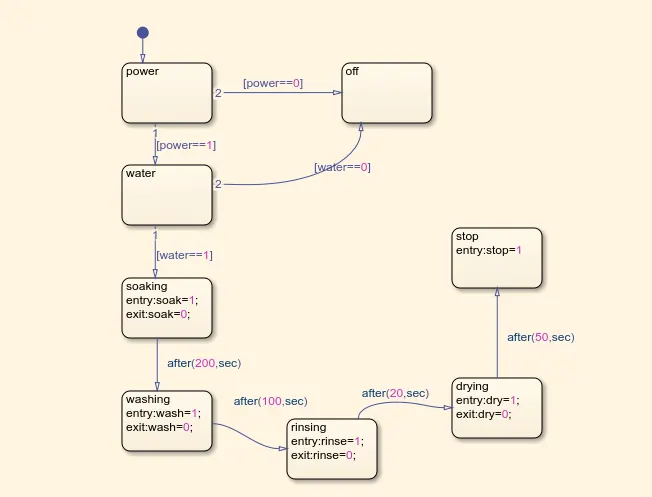
1) In a washing machine the soaking, washing, rinsing, drying and water filling etc are the various processes. As per the logic of operation it is designed in the chart block of state flow.
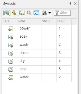
2)The various input and output pins are created using symbols pane.
Output:
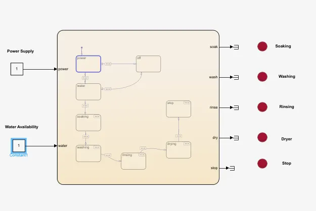
1)When the power and water is present in the washing machine, then the system is in ON state.
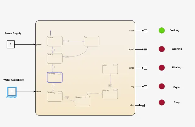
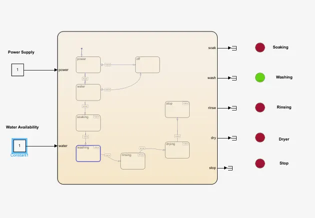
2)Soaking is done for a time period of 200 seconds and the washing for 100 seconds respectively.
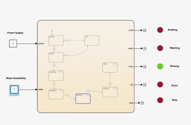
3) Rinsing is done for 20 seconds and drying for 50 seconds.
4)Once the drying process is done , then the system stops the process.
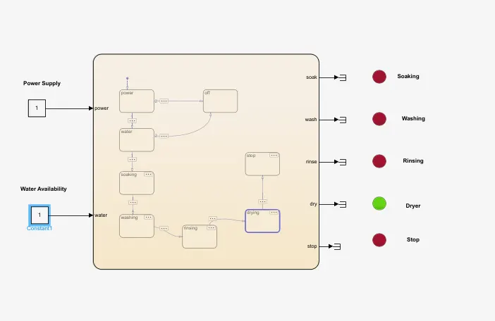
5)In the below model we can see that the system stops after completing all the processes.
Result:
Thus the implementation of control logic in a washing machine using stateflow is done and the required output are obtained as per the given data.
2)Simulink chart for the “Gear shift” logic:
Aim:
To give speed input while the simulation is running & display the gear number.
Objective:
To make a Simulink chart for the “Gear shift” logic .
Given Data:
Speed Range(kmph) Gear
0 to 15 1
16 to 25 2
26 to 40 3
41 to 60 4
Above 61 5
Principle:
1)State flow is a control logic tool used to model reactive systems via state machines and flow charts wthin a Simulink model.
2)Simscape is used to create models of physical systems within the simulink.
3)As the gear number increases the speed of the system increases. The system is designed using the chart model and the output is viewed using the connected speedometer while the simulation is running.
Simulation:
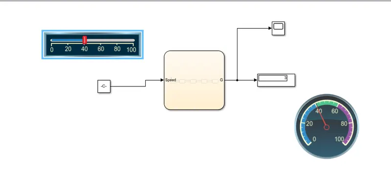
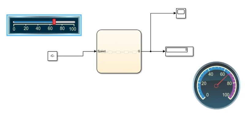
1)The above simulation model represents the simulation of the Gear shift logic.
Input:
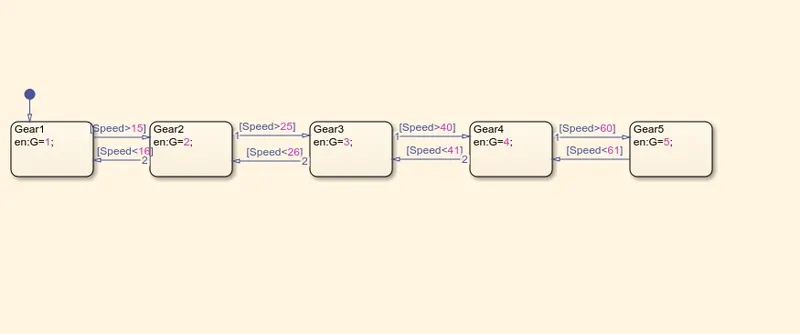
2) As per the given gear and speed data the logic control is designed in the chart block by assingng the parameters.
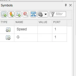
3)The input and output pins of the control logic created in the chart is made in symbol pane. Then a scope and display are connected to view the output speed of the system.
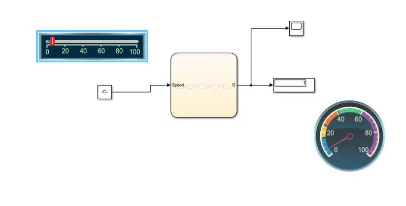
2) When the speed is between 0 to 15 kmph the vehicle moves in 1st gear as shown in the above model.
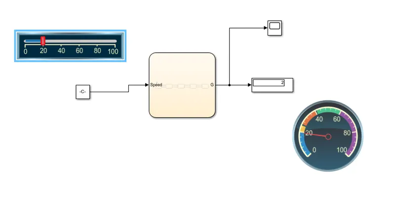
3) Similarly when the vehicle moves between 16 to 25 kmph speed indicates second gear.
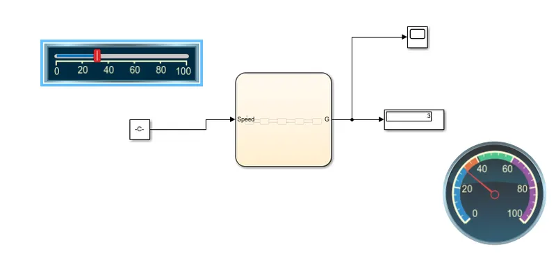
4) Speed between 26 to 40 kmph represents 3rd gear.
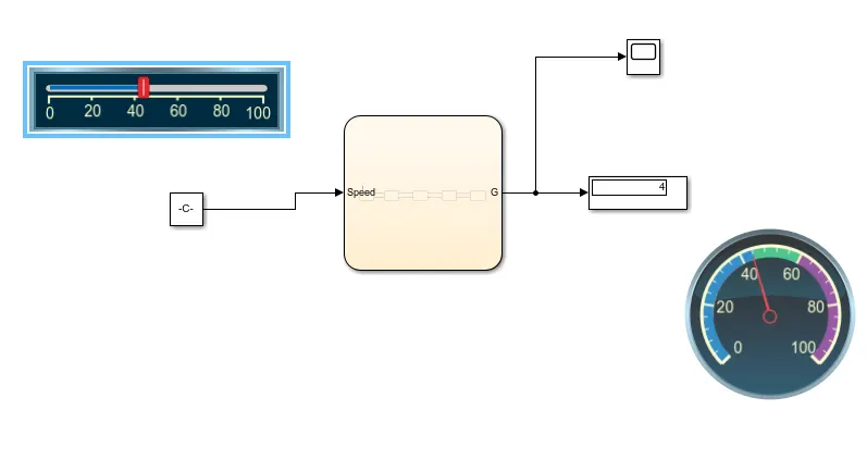
5) When the system moves wth the speed between 41 to 60 kmph represents 4 th gear.
6) When the system runs above 61kmph it represents the 5 th gear.
7) A speedometer is connected to display the speed while changing gears.
Output:
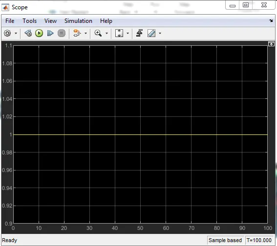
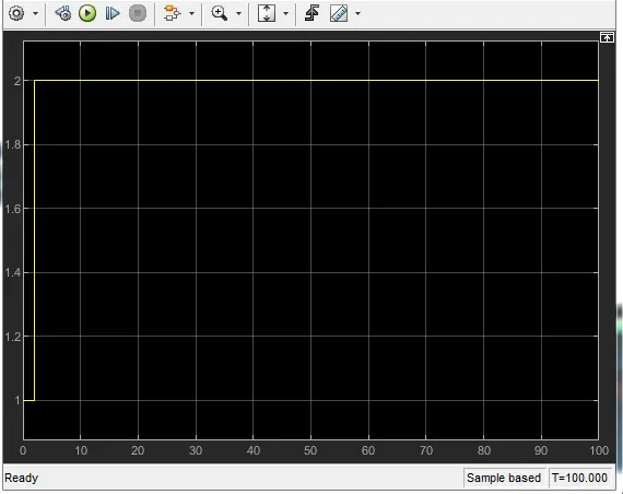
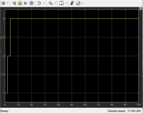
The following are the output obtainted by viewing through scope block:
1)Output for gear 1
2) Output for gear 2
3) Output for gear 3
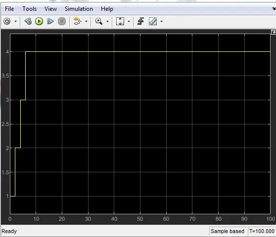
4) Output for gear 4
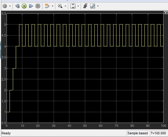
5) Output for gear 5
Result:
Thus while running the simulation the speed input is given and the gear number is displayed.