Week-7 Challenge: DC Motor Control
Q.NO 1 A. Explain a MATLAB demo model named ‘Speed control of a DC motor using BJT H-bridge’.
B. Comment on the armature current shoot-up from the scope results.
C. Refer to the help section of ‘The Four-Quadrant Chopper DC Drive (DC7) block’. Compare it with the H-bridge model.
A.Explain a MATLAB demo model named ‘Speed control of a DC motor using BJT H-bridge’.
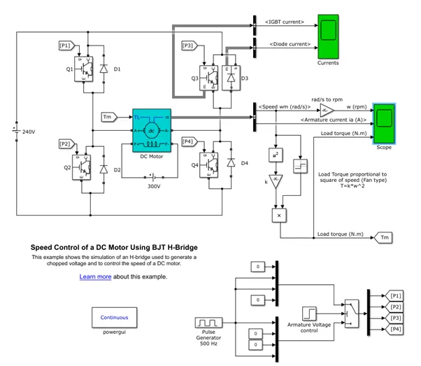
Figure 1. Speed Control of a DC Motor Using BJT H-Bridge.
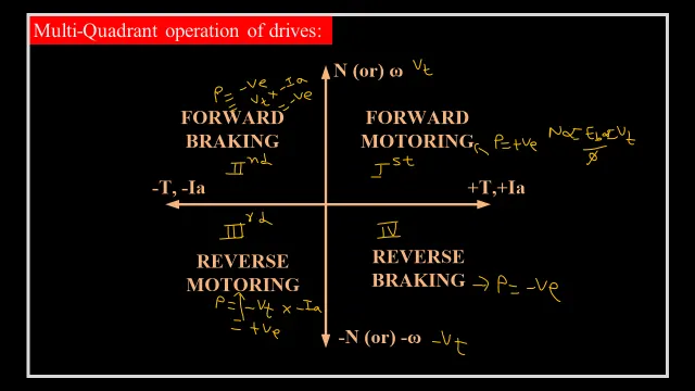
Figure 2. Four quadrants of Motor operation.
For 0.75 Duty cycle:
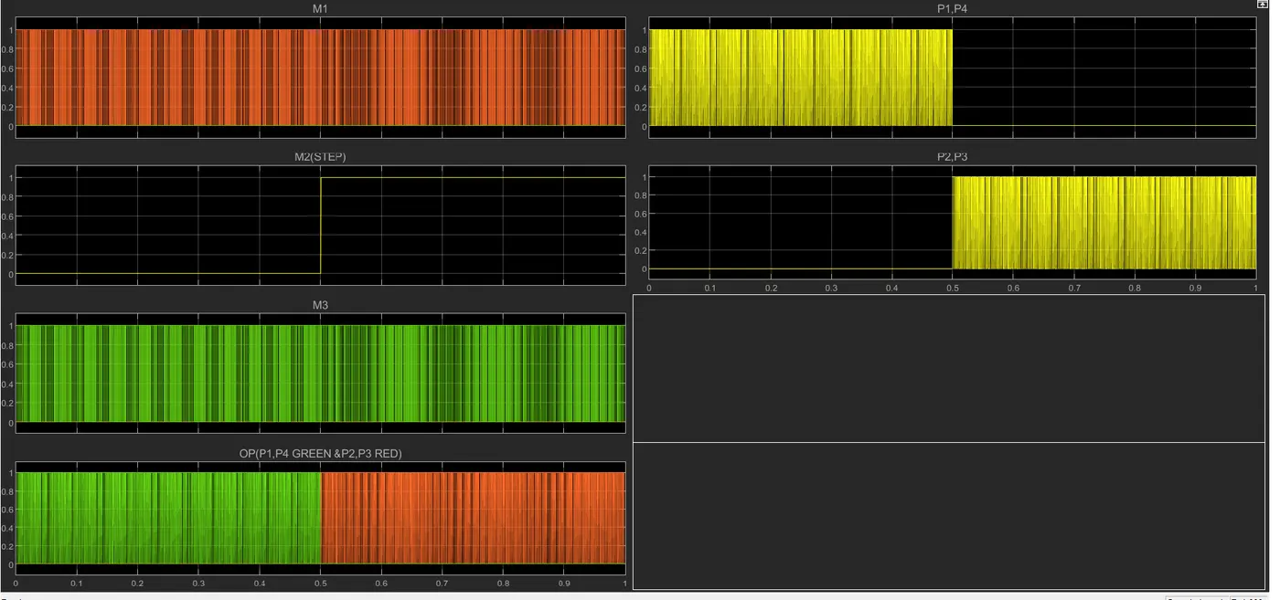
PWM PULSES:
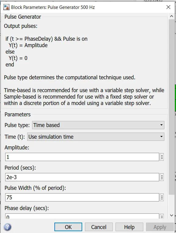
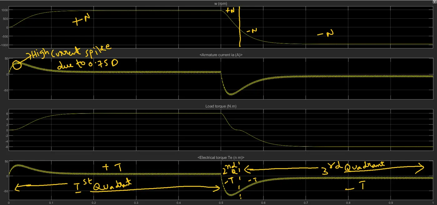
Figure 3. Waveforms corresponding to 0.75 Duty cycle.
B. Comment on the armature current shoot-up from the scope results.
It is observed that the armature current has a high spike at the starting of the motor which is nearly equal to 40A. This was happened because of the high duty cycle. Higher the duty cycle the output voltage is also high followed by armature current. To reduce the spike duty cycle must be reduced. now we will see for 0.5 Duty cycle.
For 0.5D:
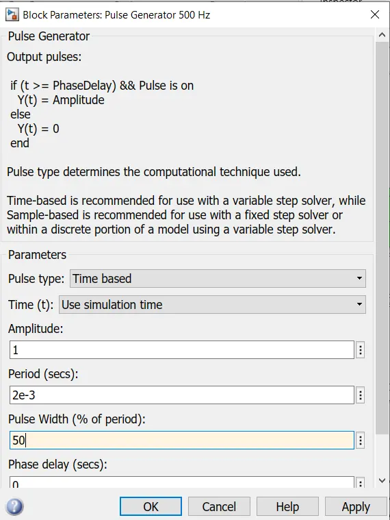
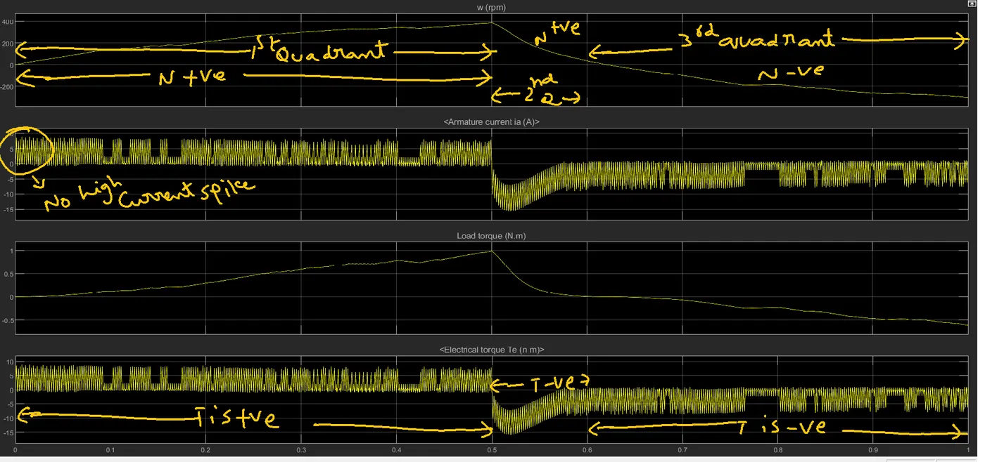
Figure 4. Waveforms corresponding to 0.5 Duty cycle.
In this case, it is observed the current waveform does not have of any current spike because in this case the duty-cycle is 50% which is less than that of the previous case. with this duty cycle also only 3 Quadrants of operation are present but 4th quadrant is absent.
For 0.25D:
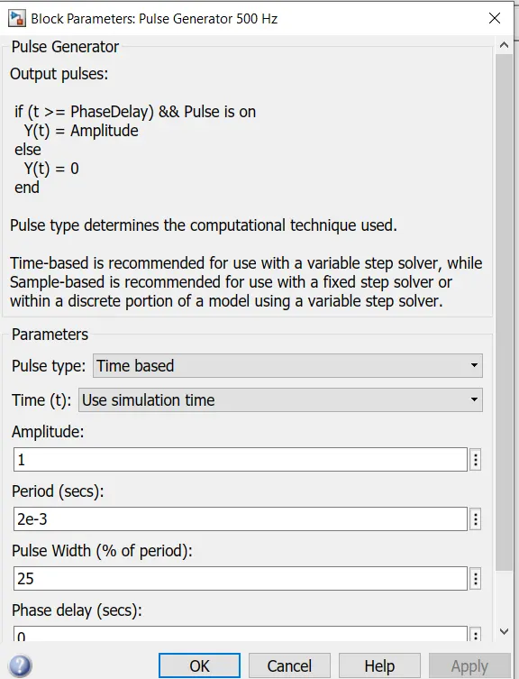
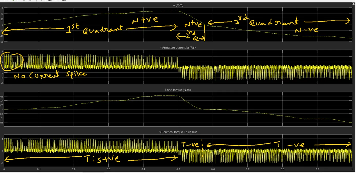
Figure 5. Waveforms corresponding to 0.25 Duty cycle.
In this case, it is observed that the current waveform does not have any current spike because in this case, the duty-cycle is 25% which is less than that of the previous case. with this duty cycle also only 3 Quadrants of operation are present but 4th quadrant is absent.
|
S.No |
Duty Cyle |
Max Speed(RPM) |
Armature Current(A) shoot Up |
|
1 |
75% |
1000 RPM |
Yes (40A) |
|
2 |
50% |
400RPM |
NO |
|
3 |
25% |
50RPM |
NO |
Disadvantages:
1. 4 Quadrant operation is not present.
2 . No closed-loop control.
C. Refer to the help section of ‘The Four-Quadrant Chopper DC Drive (DC7) block’. Compare it with the H-bridge model.
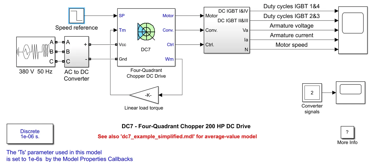
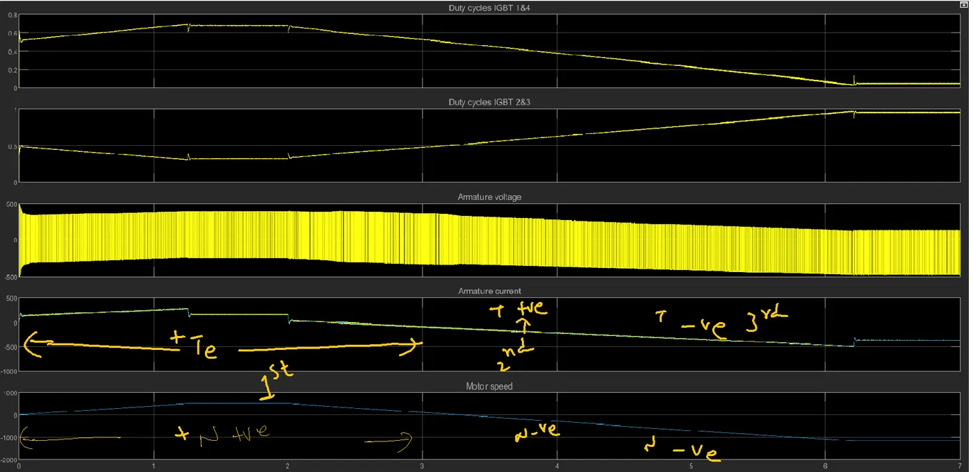
Figure 6. Waveforms corresponding to step signal as speed input.
- The main difference between BJT H-Bridge and four-quadrant chopper is control (speed and current control). With the step signal also here I am getting only three quadrant operations only. To get the four-quadrant operation speed has to be changed.
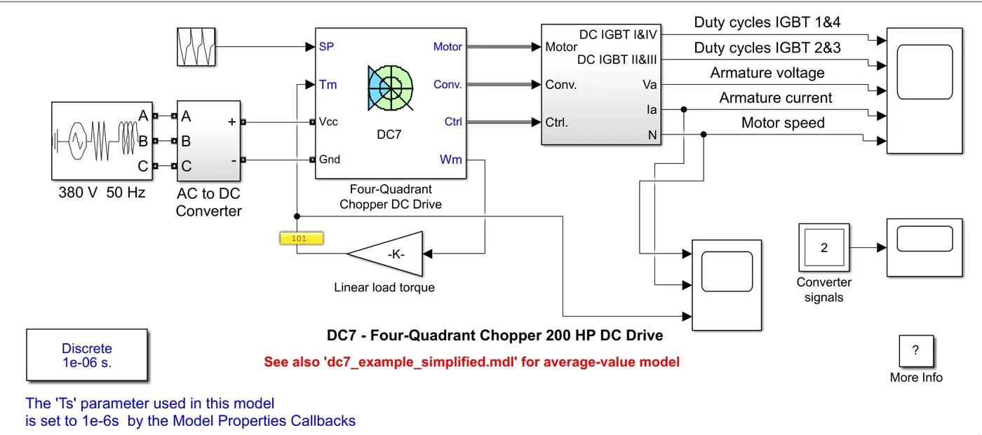
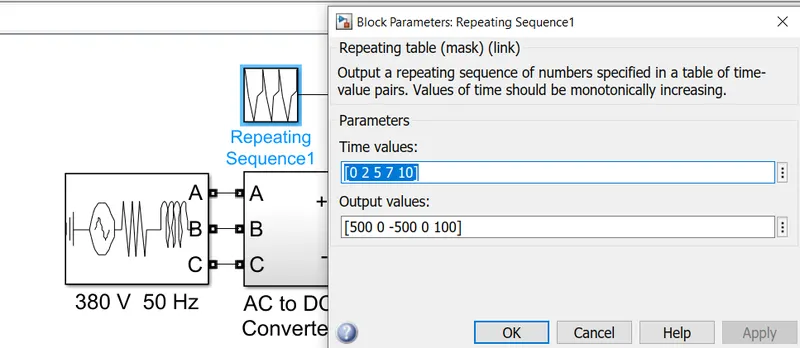
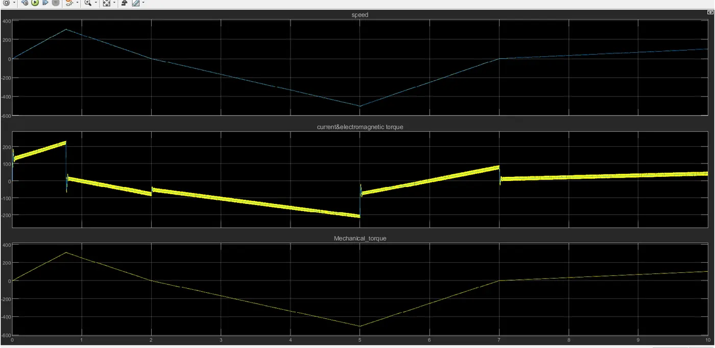
Figure 7. Waveforms corresponding to Repeated signal as speed input.
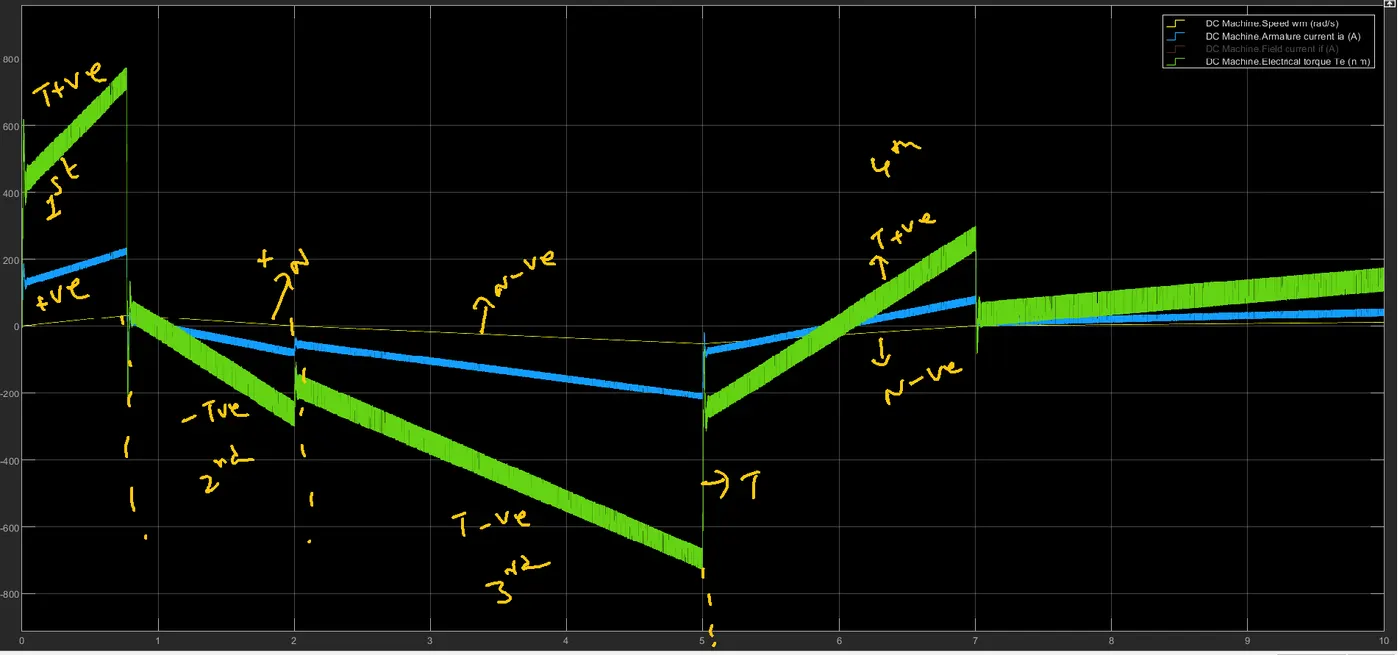
Figure 8. zoomed view of Figure 7.
In this case, a 4 quadrant operation is presented due to the repeating signal mentioned above. Figure 8 shows clearly mentioned 4 quadrants. Figure 8 speed units are in terms of rad/sec and in figure 7 speed units are RPM. With H-Bridge speed signal cant be changed and but in the case of a 4 quadrant chopper drive speed signal can be changed.
2. Develop a 2-quadrant chopper using simulink & explain the working of the same with the relevant results. (Refer to article - Multiquadrant operation of motor)
Two quadrant Type-A chopper or Class C chopper
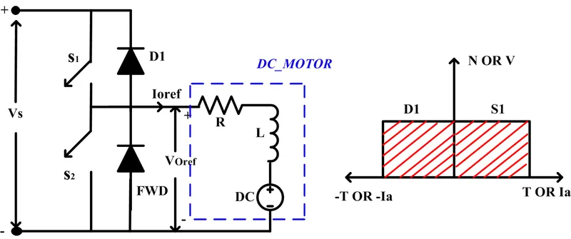
Figure 9. Two quadrant Type-A chopper.
Mode1: When S1 is ON and the remaining devices are in OFF state.
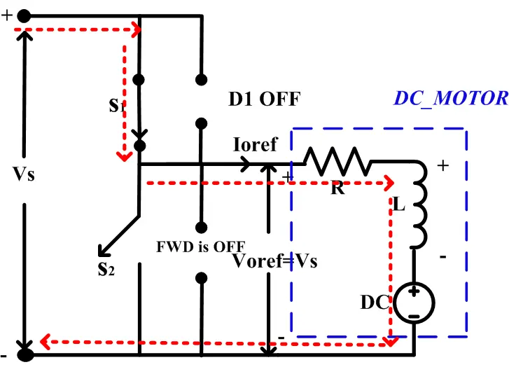
Figure 10. Mode 1 Operation of Two quadrant Type-A chopper.
When the switch S1 is ON the current flows from +Vs-S1-MOTOR-(-Vs). In this case, the Motor inductance is energized and the polarities are shown in figure 10. In this case, Motor voltage, speed, and torque are positive. Hence first quadrant operation is obtained.
Mode 2: When S1 is OFF and Freewheeling Diode(FWD) is ON:
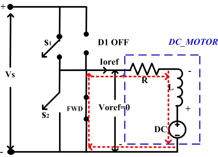
Figure 10. Mode 2 Operation of Two quadrant Type-A chopper.
In this mode operation, S1 is OFF and the polarities of the Inductor are reversed. The armature current will flows through the freewheeling diode(FWD) which is as shown in figure 10 and the motor will maintain the same speed. The freewheeling diode is connected across motor terminals due to the FWD Conduction the motor voltage or Vo is 0. Finally, with this mode of operation, no Quadrant operation is present.
Mode 3: When S2 is ON
At the end of mode 2 (or starting of Mode 3) the polarities are again reversed which is as shown in figure 11.
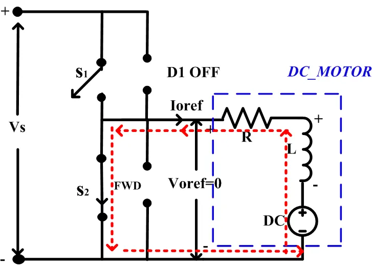
Figure 11. Mode 3 Operation of Two quadrant Type-A chopper.
When the switch S2 is ON the current flows through +L-R-S2-DC-(-L). In this case, S2 is connected across the motor terminals and due to conduction Motor voltage Vo=0 and no quadrant operation here. It is observed that the current direction in this mode is opposite to that of reference polarity and followed by electromagnetic torque.
Mode 4: When S2 is OFF and D2 is ON
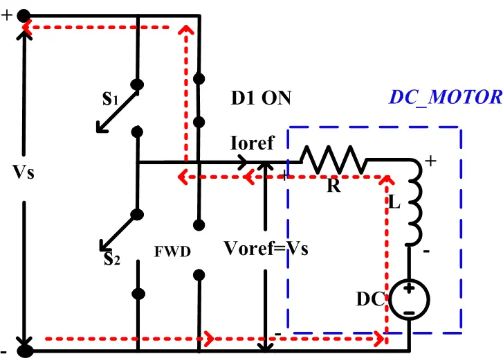
Figure 12. Mode 4 Operation of Two quadrant Type-A chopper.
In this mode, S2 is OFF and the energy stored in the inductor is discharged through the diode D2 and the current path is as shown in figure 12. The current direction is opposite to the reference direction followed by the electromagnetic torque and the output voltage polarities are the same as that of the reference direction. Hence, a second quadrant operation is present.
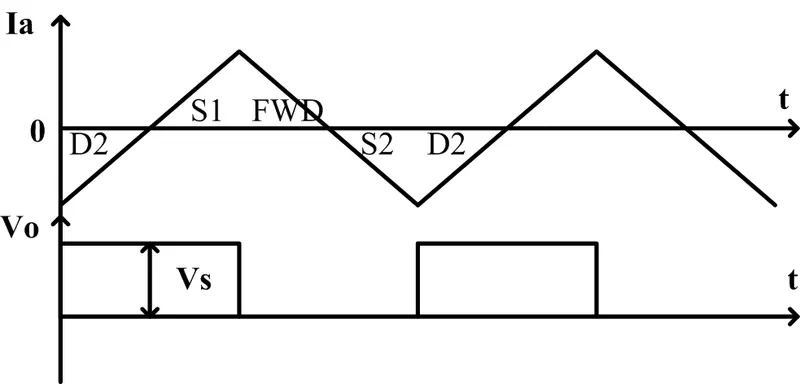
Figure 13. Theoretical waveforms of Class C chopper.
The output voltage Vo is given by Vo=DVs. Where Vs= voltage source and D=Duty Cycle.
Now this converter is implemented using MATLAB software
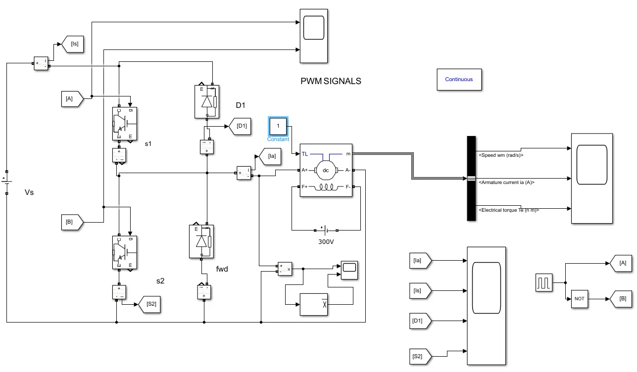
Figure 14. Class C or Two quadrant type A chopper drive.
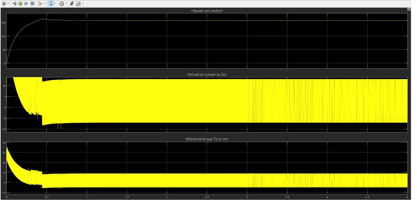
Figure 15. Waveforms of Class C or Two quadrant type A chopper drive.
From the above waveforms, it is observed that Speed (Rad/sec) is always positive but Torque is positive and negative.
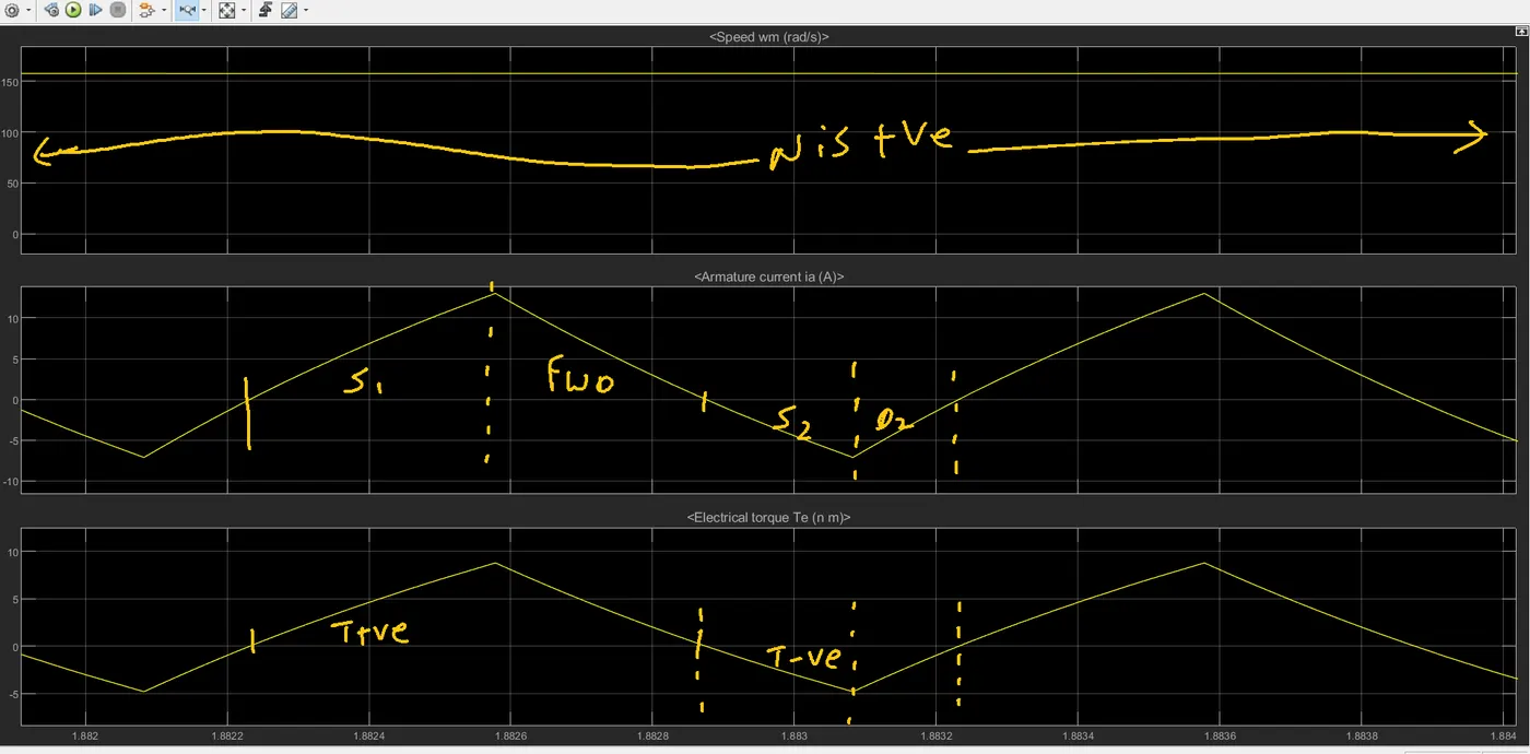
Figure 16. Zoomed view of Figure 14.
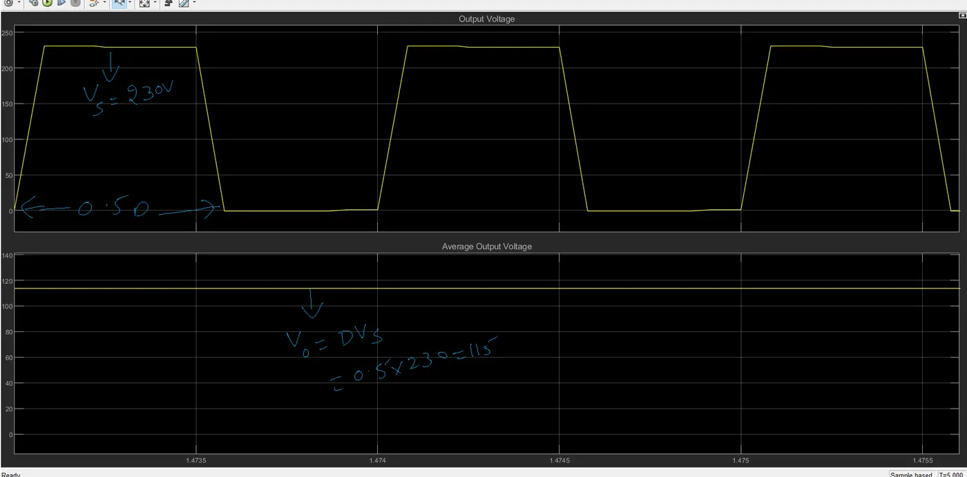
Figure 17. Output voltage and Average output Voltage
The above-simulated waveforms are matched with theoretical waveforms shown in figure 13.
3. Explain in a brief the operation of the BLDC motor.
A brushless dc motor is a polyphase synchronous motor with a permanent-magnet rotor. This motor cannot operate without its electronic controller. Therefore, a brushless dc motor is a motor drive system that combines into one unit an ac motor, solid-state inverter, and a rotor position sensor. The solid-state inverter uses transistors for low-power drives and thyristors for high-power drives. The rotor position sensor monitors the shaft position and sends the control signals for turning on the controlled switches of the inverter in an appropriate sequence.
A brushless dc motor is also viewed as inside-out dc motor because its construction is opposite to that of a conventional DC Motor. It has permanent magnet field poles on the rotor and polyphase armature winding on the stator. The function of a mechanical commutator in a conventional dc motor is now performed by an electronics commutator in a brushless dc motor. This motor possesses several advantages over the conventional dc motor as outlined below.
a) As no mechanical commutator and brushes are required, it has longer life.
b) Problems relating to radio frequency and electromagnetic interference are minimized.
c) It can run at speeds much higher than those obtained in a conventional dc motor.
d) Brushless dc motor is more efficient.
Basic Operating Principle:
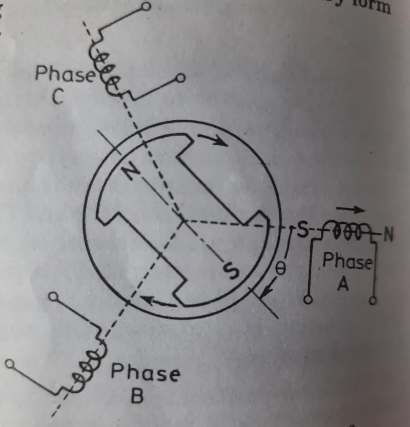
The below figure shows an elementary form of the three-phase stator winding and the permanent magnet rotor with two poles. When phase A is energized, stator S and N poles are created as shown in figure 18. Stator S pole repells rotor S pole and attracts rotor N Pole, thus producing clockwise torque. The magnitudes of this torque are given by
`Te=K1phisphirsin theta to1`
Where `phis=`stator field flux
`phir=`rotor field flux
`theta=`torque angle
K1= torque constant
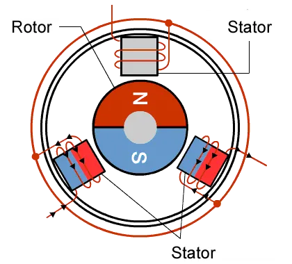
In this animation, it is observed that stator poles are changing(red and blue). The pole formation is depends upon the current flowing through in it. For the positive half cycle red color and the negative half cycle, blue color will form. Here hall effect sensors are required to sense the shaft position.
Figure 18. An elementary form of brushless DC Motor.
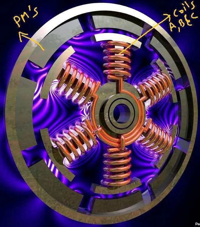
Figure 19 rotor and stator coil image of BLDC Motor.
The BLDC Stator winding will excite at a time with single or two phases. Here, the operation is discussed when the stator is excited by only one phase.
case i: When A phase is excited
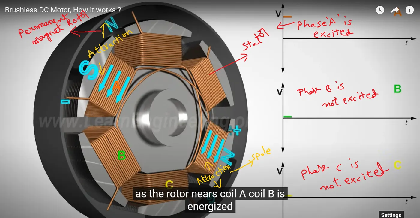
Figure 20. when stator phase A is excited only.
When phase A is excited, the Rotor N pole is attracted with A phase stator S pole and also rotor S pole is attracted with A phase Stator N pole. The corresponding diagram is as shown in figure 20.
case ii: When B phase is excited
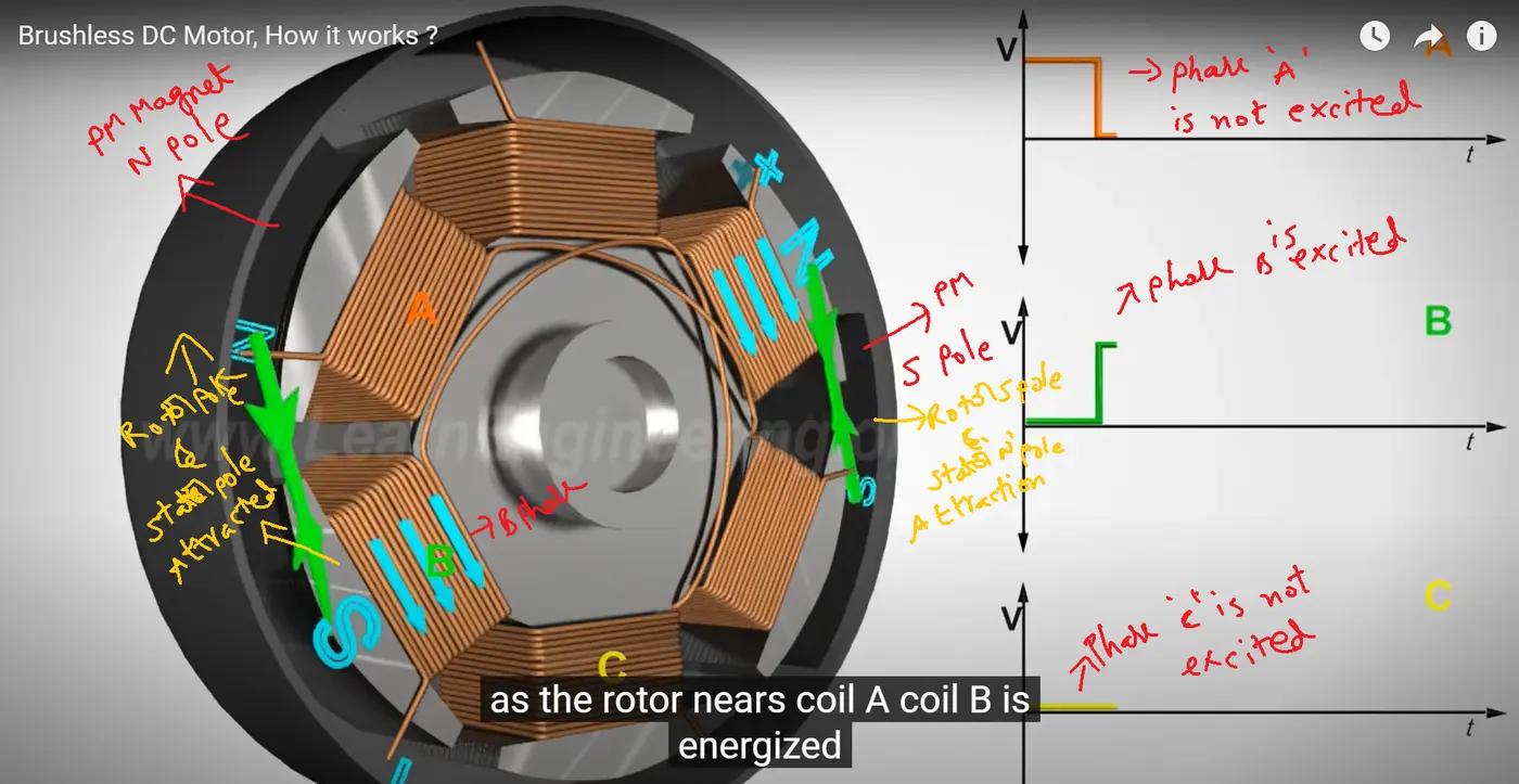
Figure 21. when stator phase B is excited only.
When phase B is excited, the Rotor N pole is attracted with the B phase stator S pole and also rotor S pole is attracted with the B phase Stator N pole. The corresponding diagram is shown in figure 21.
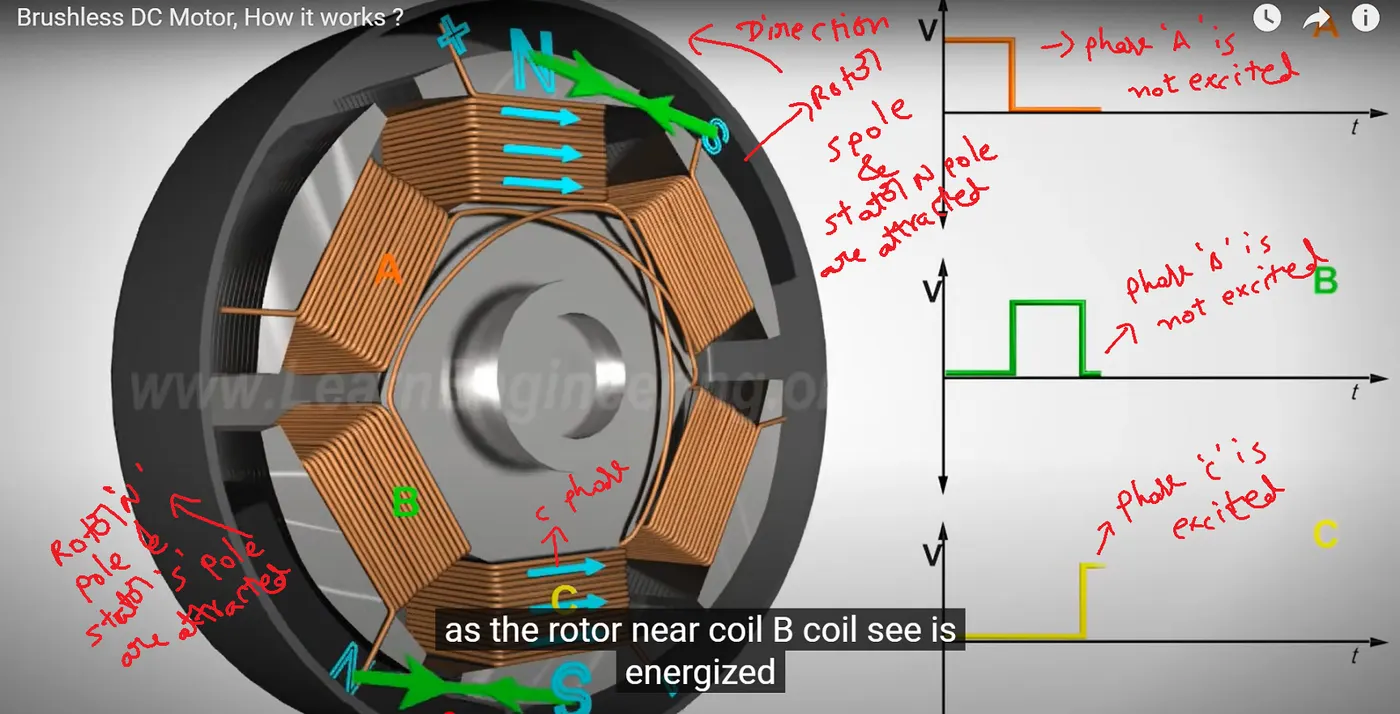
Figure 22. when stator phase C is excited only.
When phase C is excited, the Rotor N pole is attracted with the C phase stator S pole and also rotor S pole is attracted with the C phase Stator N pole. The corresponding diagram is shown in figure 22.
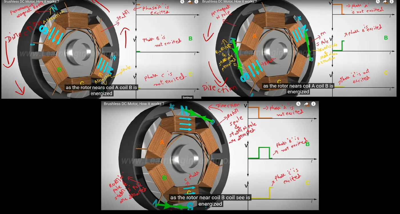
Figure 23. Putting all together.
The above figure shows that all three modes are presented in a single pic. The major disadvantage, if only one stator winding will excite, is the power output is very less. Hence now we are moving to 2 phase excitation. By using three-phase excitation force will not produce in the same direction.
This figure shows the basic principle of nearly all kinds of motor rotations. The rotor and the stator in the motor generate the
interactive force and the rotor spins as long as the force is in the same direction.
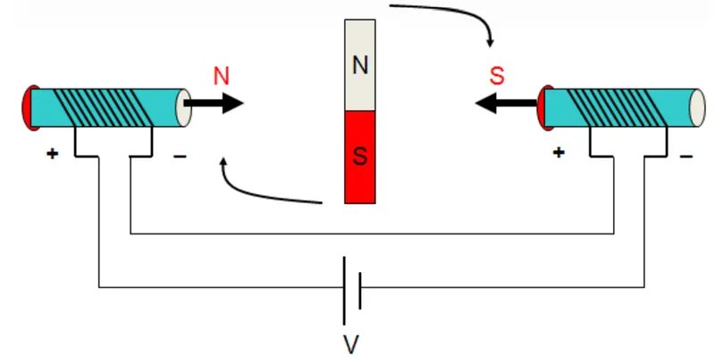
Figure 24. Two coils are excited by a voltage source.
As seen from Figure 24, the rotor spins in the clockwise direction because the force is in the direction of the rotor spin.
However, after rotating 180°, the direction of the force changes, preventing the rotor from spinning and trying to drag it back.
At last, the rotor will not spin in the same direction but just sways. One effective way of keeping the force in the same direction is to change the current direction in the coil at the same time when the force direction changes. See this figure. This process is called commutation.
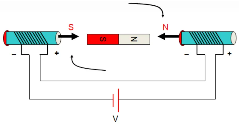
Figure 25. Motor Commutation.
Here it is observed that at a time only two phases will excite the remaining one phase won't excite to achieve mechanical rotation.
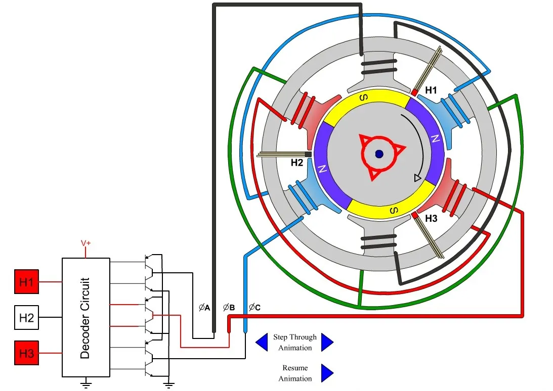
Figure 26. BLDC Motor along with Hall effect sensors.
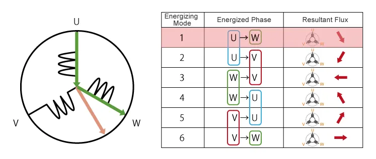
Figure 27. Two-phase field direction.
By using this animation we could know the resultant field direction. In three phase 120 degrees mode at a time only two phases will excite. The following diagram shows the 3 phase 120 degree inverter.
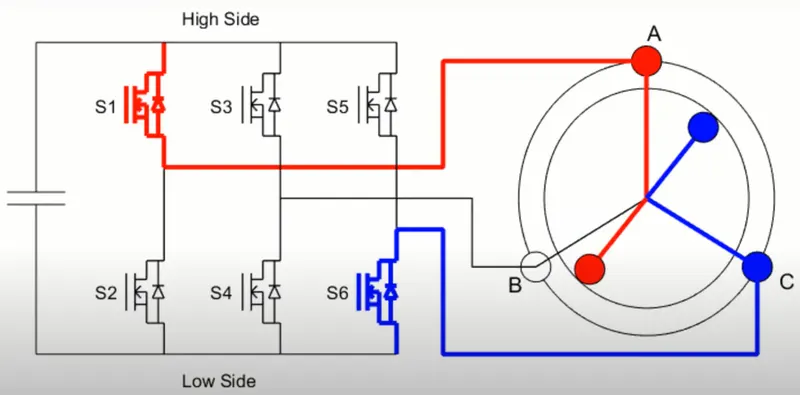
Figure 28. 3 Phase inverter fed BLDC motor for AC phase excitation.
Here i am showing only one diagram for understanding. Depending upon hall effect sensors other phases will excite.
Features of BLDC Motors:
- Reliable, Efficient and less noise.
- Lighter than Brushed DC Motor.
- BLDC Motor for reliability and operation.
- BLDC has permanent magnets.
- No commutator and brush arrangement.
- Maintenance-free.
- High starting torque and high efficiency (when used inverter only not from direct source).
- Most preferred for Electric Vehicles.