Week-7 Challenge: DC Motor Control
(1) A. Explain a MATLAB demo model named ‘Speed control of a DC motor using BJT H-bridge’.
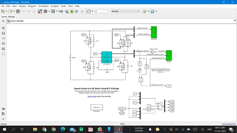
Working:
- In the above DC motor using BJT H bridge model voltage is generated from the pulse generator giving the input supply and duty cycle is assigned in pulse genrator. the switch block is connected to the pulse genrator through armature voltage control block. A switch block contain 4 power supply namely [p1,p2,p3,p4] these four input are on goto from block. this four input are connected to transistor Q1,Q2,Q3,Q4 through from block and from block receving signal from the goto block.
- In the H bridge arragement transistor allows a circuit full control of DC motor.
- Dc motor connected to battery and mechanical input of DC motor is initiated torque. and torque of DC motor also switched by goto and from block.
- in this model 4 transistor operates simultaneously , when Q1 and Q4 are fired, positive voltage applied to motor and D2 and D3 diode are operates as free wheeling diode ,when diode Q1 and Q4 are off.
- then diode Q2 and Q3 are fired, a negative voltage is appiled to motor and D1 and D4 are operatesa as free wheeling diode then Q2 and Q3 are off.
- Switching: Forward motoring: Q1 andQ4, Reverse motoring: Q2 and Q3.
- the output of this model connected to Bus selector to measure speed, load torque, armature current,IGBT current and diode current.
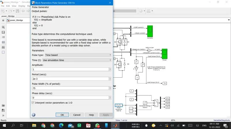
Pulse generator:
(B). Comment on the armature current shoot-up from the scope results.
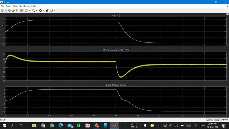
the above graph shows the speed armature current and load torque. speed and armature current is obtained by the Dc motor and load torque is calculated by load torque is proportional to square of speed. during time period 0 to 0.5 sudden shootup is occur. speed, armature current and load torque are positive for time period 0.5 sec. after 0.5 sec speed, armature currents amd load torque are decreases to negative value this happens pulse generator step time.
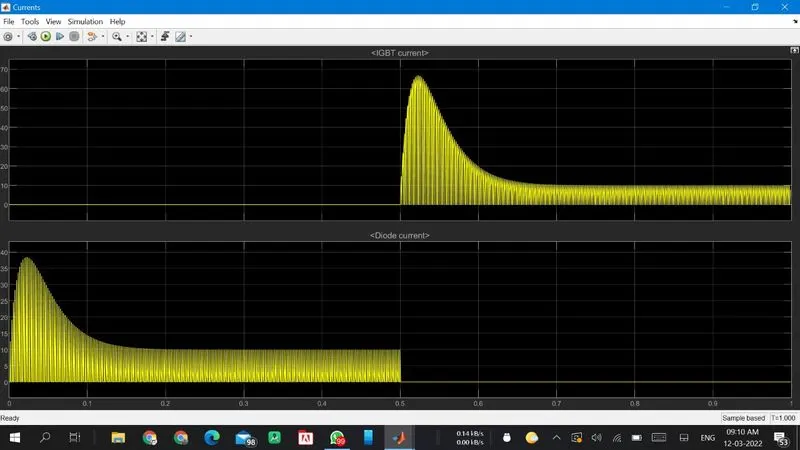
the above result shows the speed control if BJT H bridge for diode and IGBT currents. the scope shows IGBT currents and diode currents passed in Q3 and D3. when switch Q3 is off on starting condition of current flow and diode current on that stage. time 0 to 0.5 sec D3 is on are according to given pulse generator and after 0.5 sec D3 is off and IGBT currents is acted after 0.5 sec and Q3 is on.
(C) Refer to the help section of ‘The Four-Quadrant Chopper DC Drive (DC7) block’. Compare it with the H-bridge model.
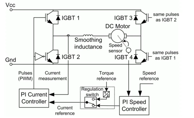
- The four quadrant chopper DC drive (DC7) block represents a four quadrants dc supplied chopper drive for Dc motors . this drives closed loop speed control with four quadrant operation. the speed control loop output the refrence armature currents of the machine, using PI controller the chopper duty cycle corresponding to the armature current divided. this duty cycle compared with sawtooth carrier signal to obtain required PWM signal for the chopper.
-
the main advantages of of this drive compared with other DC drive. this drive are operated all four quadrants ,and this drive used in high swiching frequency DC to Dc converter, a lower armature currents rippel is obtained.four switching devices are reqired which increases the complexity of drive system.
-
armature voltage is provided by an IGBT converter controlled two PI regulators.the DC bus voltage during dynamic braking mode, braking chopper is added between diode rectifier and DC7 block.
- two regulator used in th model 1. current regulator 2. speed regulator
- current regulator: it controlls the armature currents by computing the appropriate duty ratioof 5 khz pulses of 4 IGBT devices , the instantaneous pulse value of IGBT devices 1 and 4 are opposite to IGBT devices 2 and 3 . this generating average armature voltage needed to obtained desired armature currents.
- speed regulator: output of the armature currents reference used by the current controlled in order to obtaining electromagnetic torque needed to reach desire speed. the speed refrence change the rate follows acceleration and deacceleration ramps to avoid sudden reference changes that could cause armature over current of the system.
comparison with H bridge:
- this machine is seperately excited with constant DC field voltage source.there is no filed voltage control.by default the field current is set to its stedy state value when starting of simulation.
- the DC7 is capable operating in all 4 quadrants. they are forword braking, reverse braking,forword motoring and reverse motoring. a motor opertes in two modes motoring and braking. a motor drive capable of operting in both direction of rotation and produced motoring and regenration is called as four quadrants variable speed drive.
- the efficiency is high in chopper compare with H bridge chopper.
- in battery technology system charger used in EV charging uses H bridge circuits. four quadrants operation is used for industrial and commercial application.
- the efficiency of four quadrants chopper is high compared with H bridge drive.
- in H bridge source is fixed DC supply and the source is used in four quadrants chopper drive source is AC supply which can be rectified to DC varying supply.
- in BJT h bridge drive armature currents shoot up during the phase transition and four quadrants chopper drive armature currents not shoot up to the value of BJT H bridge but for low voltage value is negligible.
2. Develop a 2-quadrant chopper using simulink & explain the working of the same with the relevant results.
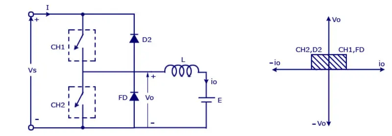
- type c chopper with can operates first as well as second quadrants this basically means that power can be flow either source to load or load to source in this chopper.this chopper called as two quadrant class a chopper.
- chopper CH1 is a free wheeling diode and load are forming class B chopper. both choppers are connected in parallel. first quadrant operation switch ON CH1 chopper and second quadrant operation switch on CH2 chopper.
- CH1 is ON: when CH1 is on source Vs is connected to the load and load voltage is equal to source voltage.the direction of load currents is from source to load.when CH1 is off free wheeling diode gets forward biased and hence short to load, therefore output voltage becomes zero. thus the average output voltage Vo and currents Io are positive and hence operation of the chopper in first quadrant.
- CH2 is On: whwn chopper Ch2 is on load DC source E drives drives current through CH2 and load. the direction of the currents Io will be opposite and hence assumed negative.output voltage Vo is zero during this time. when CH2 is off diode D2 gets forward bias and hence currents into the source from the load. thius operation of chopper in second quadrant.
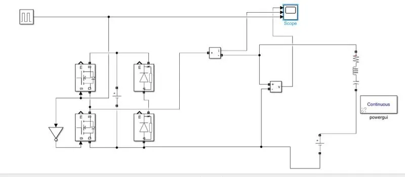
above simulation model 2 quadrant operation of the chopper. pulse generator give to not gate to prevent misfiring of the mosfet they not conduct at same time which result in short circuit.
Simulation output:
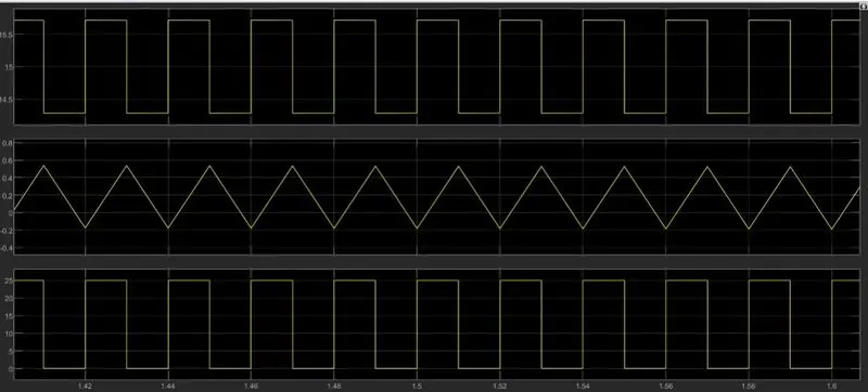
in the above result voltage is always positive and currents continous positive and negative.
(3). Explain in a brief about operation of BLDC motor.
A Brushless DC Motor, BLDC accomplishes commutation electronically using rotor position feedback to determine when to switch the current. The BLDC motor is electrically commutated by power switches instead of brushes
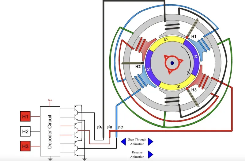
construction: Brushless DC motors have been a much focused area for numerous motor manufacturers as these motors are increasingly the preferred choice in many applications, especially in the field of motor control technology. BLDC motors are superior to brushed DC motors in many ways, such as ability to operate at high speeds, high efficiency, and better heat dissipation.
They are an indispensable part of modern drive technology, most commonly employed for actuating drives, machine tools, electric propulsion, robotics, computer peripherals and also for electrical power generation. With the development of sensorless technology besides digital control, these motors become so effective in terms of total system cost, size and reliability.
Working:
BLDC motor works on the principle same as the conventional DC motor, the Lorentz force law which states that whenever a current carrying conductor placed in a magnetic field it experiences a force. As a consequence of reaction force, the magnet will experience an equal and opposite force. In case BLDC motor, the current carrying conductor is stationary while the permanent magnet moves.
When the stator coils are electrically switched by a supply source, it becomes electromagnet and starts producing the uniform field in the air gap. Though the source of supply is DC, switching makes to generate an AC voltage waveform with trapezoidal shape. Due to the force of interaction between electromagnet stator and permanent magnet rotor, the rotor continues to rotate.
Consider the figure below in which motor stator is excited based on different switching states. With the switching of windings as High and Low signals, corresponding winding energized as North and South poles. The permanent magnet rotor with North and South poles align with stator poles causing motor to rotate.