Week -2
(1)Make a Simulink model of Doorbell using solenoid block with the following details:
conditions:Create a situation where the switch is closed for 2 seconds and then released.
- Block used:
Solenoid
Battery
PS Simulink converter
Switch
Pulse generator
Ideal translational motion sensor
Mechanical translational reference
Scope
Electrical reference
Solver configuration.
Simulation model:
Model Explanation:
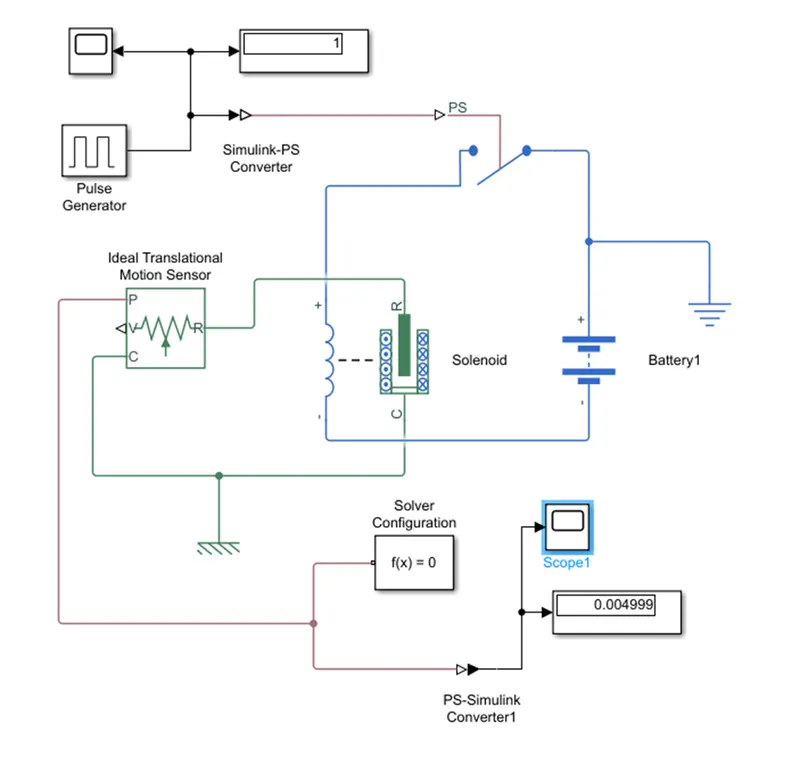
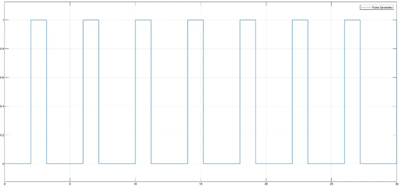
In this model we used pulse generator as input to model. Pulse generator is a timed based variable step solver. The condition the switch is closed for 2sec and then released. the model was implement as time period is 4 sec and pulse width is 40 %for 4sec .and time delay is 2sec for this model.In the model pulse generator input signal give to the ps Simulink converter
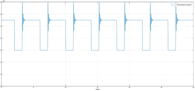
They convert physical signal to Simulink signal. This signal given to the PS switch. This is connected to solenoid and battery. solenoid is electro mechanical characteristics device. solenoid electrical terminal connected to battery and mechanical terminal connected to the translational motion sensor this sensor converts across variable measured between two mechanical nodes and control signal proportional to velocity and position. The initial position of translation motion is 5mm. the output part of translational motion connected to the solver configuration and PS Simulink converter. The output will be shown in the scope. The electrical and mechanical references connected to their circuit.
Result: (INPUT)
(OUTPUT):
(2)Thermistor to sense the temperature
Condition: Fan is ON above 25.c otherwise it OFF
Block used:
Solver configuration, Simulink PS converter, PS Simulink converter, voltage sensor, resistor, repeating sequence stair, controlled temperature source, thermistor, switch, lamp, battery
Simulation model:
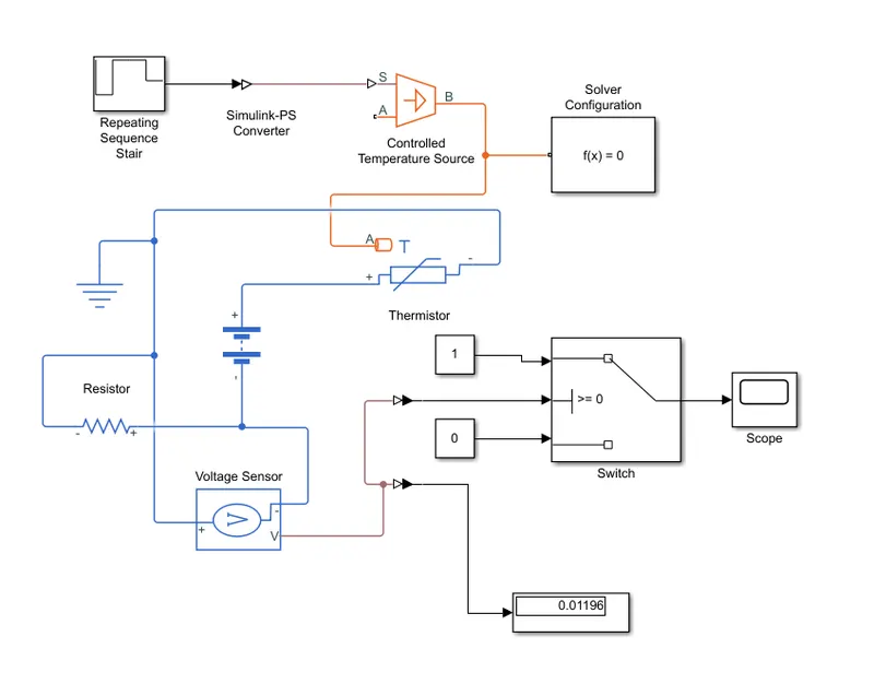
Explanation:
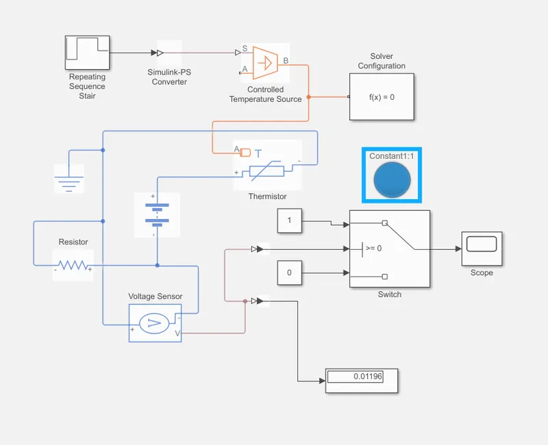
The simulation time is 30s and repeating sequence stair sample time is 10s. In this model various input given to the thermistor from the repeating sequence stair to the controlled temperature source. The repeating sequence stair set the temperature in a kelvin. This output temperature given to the PS Simulink converter they convert the Simulink signal to physical signal provided in controlled temperature source. controlled temperature source in a thermal network maintain a controlled temperature difference of heat flow rate. the output of temperature controlled sensor connected to the thermistor input terminal and output of thermistor connected resistor and voltage sensor through the battery. voltage sensor is the device converts voltage measured between any electrical connection into physical signal. The output of voltage sensor connected to the switch through PS simulating converter. The threshold voltage give to the switch 0.c and the output occurring in green signal and blue signal.
Outputs:
Green signal temperature above 25.c
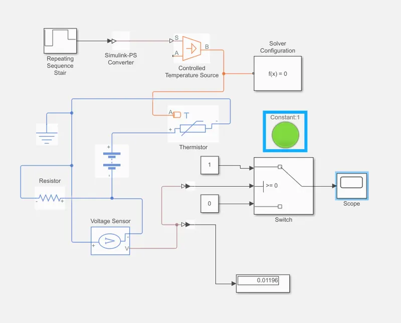
Blue signal temperature below 25.c