Week-7 Challenge: DC Motor Control
1.ANS:
Objectives:
A. Explain a MATLAB demo model named ‘Speed control of a DC motor using BJT H-bridge’.
B. Comment on the armature current shoot-up from the scope results.
C. Refer to the help section of ‘The Four-Quadrant Chopper DC Drive (DC7) block’. Compare it with the H-bridge model.
Description:
Demo model named ‘Speed control of a DC motor using BJT H-bridge’: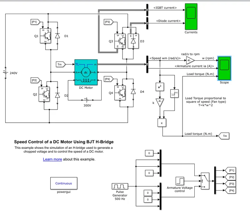
In detail of above model in Step by Step:
1) Here taken Pulse Generator of 500Hz by changing default value of 10sec to 0.002 sec and pulse with of 75% and Armature Voltage control step 0.5s time given as 0 after it rise to 1.
| Pulse Generator 500Hz | Armature Voltage control | P1 | P2 | P3 | P4 |
| 0 | 0 | 0 | 1 | 1 | 0 |
|
1 |
0 | 0 | 1 | 1 | 0 |
| 0 | 0 | 0 | 1 | 1 | 0 |
| 1 | 0 | 0 | 1 | 1 | 0 |
| 0 | 1 | 1 | 0 | 0 | 1 |
| 1 | 1 | 1 | 0 | 0 | 1 |
| 0 | 1 | 1 | 0 | 0 | 1 |
| 1 | 1 | 1 | 0 | 0 | 1 |
In truth table when state is '1' then pulse signal at 500Hz.
2) In power switching applications BJT acts as IGBT, when BJT in saturation region then forward voltage Vf developed in the collector and emitter. IGBT is driven by the gate voltage. Here H-bridge consists of 4 BJT transistors, Diode pairs.
When Q1 & Q4 are switched on then positive voltage applied to the motor, Q2 & Q3 are in off state and D2 & D3 are freewheeling diodes.
When Q2 & Q3 are switched on then negative voltage applied to the motor, Q1 & Q4 are in off state and D1 & D2 are freewheeling diodes.
3) The DC motor uses the preset model (5 HP 240V 1750 rpm). It simulates a fan type load (where Load torque is proportional to square of speed).
Results:
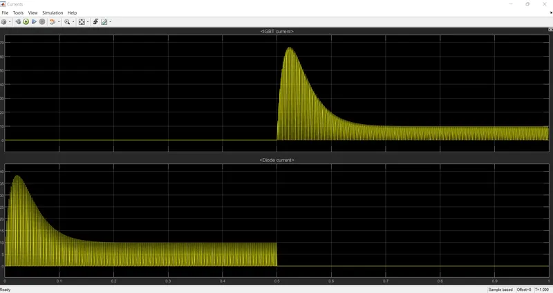
Here taken the simulation of Q3 & D3 mesurement port and observed the IGBT & Diode Current.
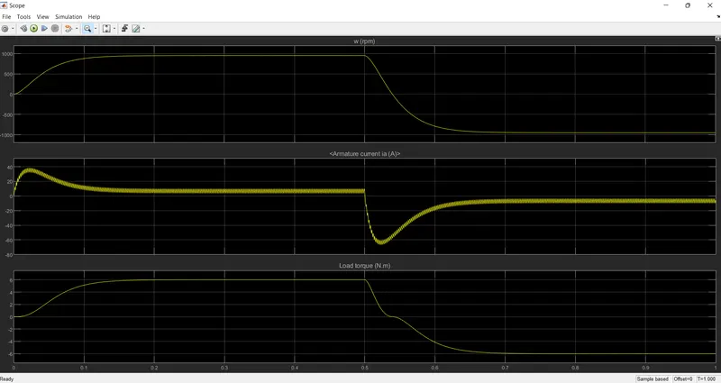
Here motor starts rotating in positive direction with duty cycle of 75%( means DC voltage of 180V). At 0.5sec the armature voltage is reversed, motor starts rotating in negative direction.
Comment on the armature current shoot-up from the scope results:
In motor, armature current I = (V-E)/R
Where, V is the voltage supplied, E is the back emf and R is the armature resistance.
Initially BACK EMF E = 0
As the motor speed increases, the back emf increses and the difference (V-E) goes on decreasing. This results in the gradual decrease of armature current until the motor attains its stable rated speed. Under this condition the armature current reaches its desired rated value.
To refer to the help section of ‘The Four-Quadrant Chopper DC Drive (DC7) block’. Compare it with the H-bridge model:
The Four-Quadrant Chopper DC Drive (DC7) block Model:
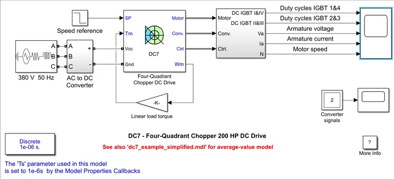
The converter is fed by a 515 V DC bus obtained by rectification of a 380 V AC 50 Hz voltage source. In order to limit the DC bus voltage during dynamic braking mode, a braking chopper has been added between the diode rectifier and the DC7 block.
The first regulator is a speed regulator, followed by a current regulator. The speed regulator outputs the armature current reference (in p.u.) used by the current controller in order to obtain the electromagnetic torque needed to reach the desired speed. The speed reference change rate follows acceleration and deceleration ramps in order to avoid sudden reference changes that could cause armature over-current and destabilize the system. The current regulator controls the armature current by computing the appropriate duty ratios of the 5 kHz pulses of the four IGBT devices (Pulse Width Modulation). For proper system behaviour, the instantaneous pulse values of IGBT devices 1 and 4 are opposite to those of IGBT devices 2 and 3. This generates the average armature voltage needed to obtain the desired armature current. In order to limit the amplitude of the current oscillations, a smoothing inductance is placed in series with the armature circuit.
Before starting the simulation, set the initial bus voltage to 515 V via the GUI block ('Initial States Setting' button and 'Cbus' variable).
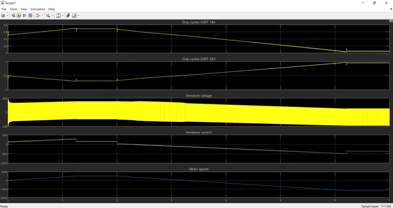
Start the simulation. You can observe the motor armature voltage and current, the four IGBT pulses and the motor speed on the scope. The current and speed references are also shown.
The motor is coupled to a linear load, which means that the mechanical torque of the load is proportional to the speed.
The speed reference is set at 500 rpm at t = 0 s. Observe that the motor speed follows the reference ramp accurately (+400 rpm/s) and reaches steady state around t = 1.3 s.
The armature current follows the current reference very well, with fast response time and small ripples. Notice that the current ripple frequency is 5 kHz.
At t = 2 s, speed reference drops to -1184 rpm. The current reference decreases to reduce the electromagnetic torque and causes the motor to decelerate with the help of the load torque.
At t = 2.2 s, the current reverses in order to produce a braking electromagnetic torque (dynamic braking mode). This causes the DC bus voltage to increase.
At t = 3.25 s, the motor reaches 0 rpm and the load torque reverses and becomes negative. The negative current now produces an accelerating electromagnetic torque to allow the motor to follow the negative speed ramp (-400 rpm/s). At t = 6.3 s, the speed reaches -1184 rpm and stabilizes around its reference.
Comparing it with the H-bridge model:
- Braking chopper circuit is added in the Four-Quadrant Chopper DC Drive (DC7) block Model remaining similar to H-bridge model.
- In four quadrant chopper DC drive consists of four quadrants like Forward Motoring, Forward Regenerative Braking, Reverse Motoring and Reverse Motoring and Reverse Regerative Braking whereas H-bridge consists of two operations Forward motoring and Reverse Motoring.
- In four quadrant chopper DC drive distributes required current supply for each sector in case of H-bridge supplies initially with high armature current after it is stabilized to rated.
- Efficiency is high in Chopper Dc drive compared to H-bridge and maintainace less in H-bridge.
- Four Quadrannt chopper circuit used in applications like compressor, Fan type load, industrial use, etc.
- H-bridge circuit used in applications like Robotic Technology, EV charging etc.
2.ANS:
AIM:To develop a 2-quadrant chopper using simulink & explain the working of the same with the relevant results.
THEORY:
CHOPPERS:
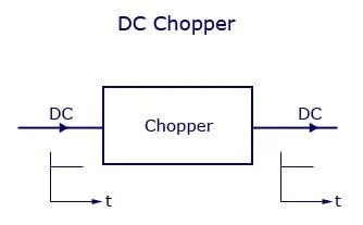
A DC chopper is a static device that converts fixed dc input voltage to a variable dc output voltage directly. A chopper can be said as dc equivalent of an ac transformer as they behave in an identical manner. This kind of choppers are more efficient as they involve one stage conversion. Just like a transformer, a chopper can be used to step up or step down the fixed dc output voltage. Choppers are used in many applications all over the world inside various electronic equipments. A chopper system has a high efficiency, fast response and a smooth control.
Principle of Chopper Operation:
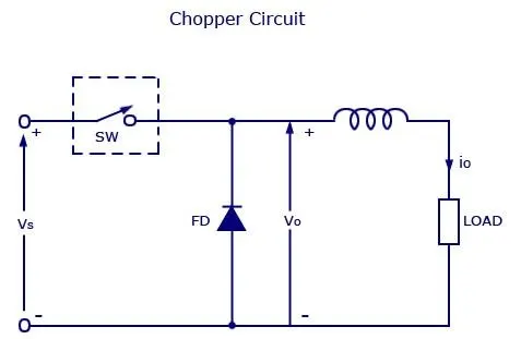
A chopper can be said as a high speed on/off semiconductor switch. Source to load connection and disconnection from load to source happens in a rapid speed. Consider the figure, here a chopped load voltage can be obtained from a constant dc supply of voltage, which has a magnitude Vs. Chopper is the one represented by “SW” inside a dotted square which can be turned on or off as desired.
2-Quadrant Chopper Circuit:
There are 2 types of 2-Quadrant
1) Type A 2-Quadrant Chopper Circuit
2) Type B 2-Quadrant Chopper Circuit
Type A 2-Quadrant Chopper Circuit:
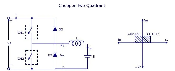
It is basically combination of first & second quadrant chooppers. In first case CH1 is ON and D2 conducts whereas ch2 is on D1 conducts in second case.
Type B 2-Quadrant Chopper Circuit:
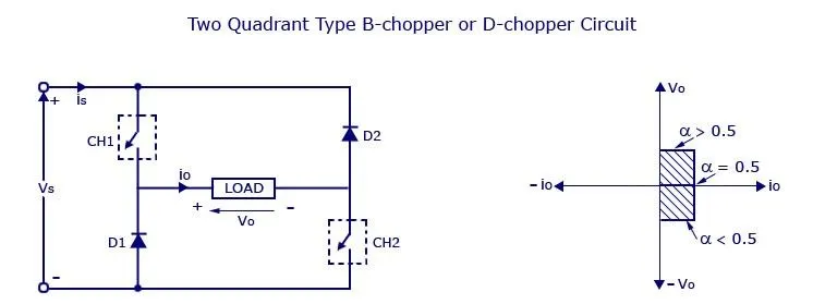
When both CH1 and CH2 are triggered simultaneously, Vo=V and curent flows. When both CH1 and CH2 are turned off the load curent continues to flow in same direction throught load D1 and D2 due to presence of inductor L.
2-quadrant chopper using simulink model:
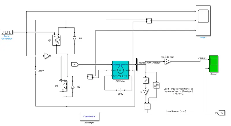
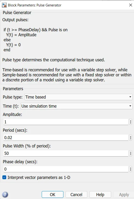
Pulse Generator parameters given as below
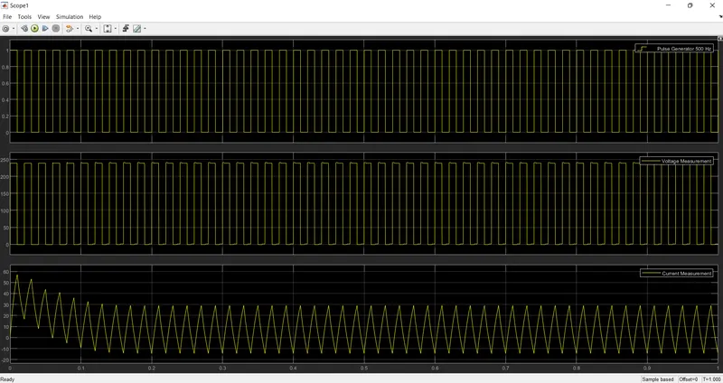
RESULTS:
Scope results shows the voltages and current measurments based on Pulse Generated
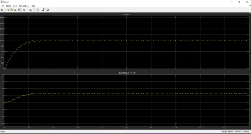
Speed-Torque characteristics:
3.ANS:
Brief about operation of BLDC motor:
BLDC motor:
A motor converts supplied electrical energy into mechanical energy. Various types of motors are in common use. Among these, brushless DC motors (BLDC) feature high efficiency and excellent controllability, and are widely used in many applications. The BLDC motor has power-saving advantages relative to other motor types.
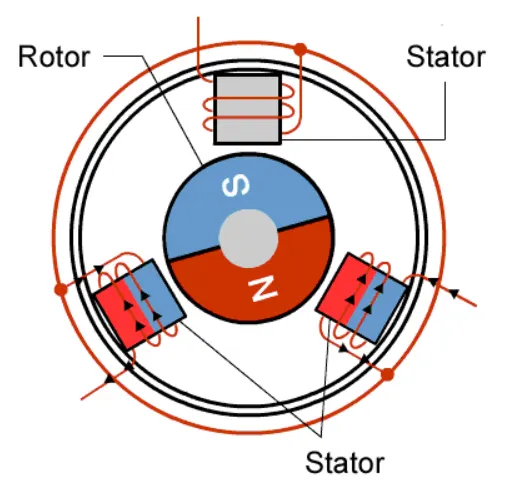
With the brushed motor, rotation is achieved by controlling the magnetic fields generated by the coils on the rotor, while the magnetic field generated by the stationary magnets remains fixed. To change the rotation speed, you change the voltage for the coils. With a BLDC motor, it is the permanent magnet that rotates; rotation is achieved by changing the direction of the magnetic fields generated by the surrounding stationary coils. To control the rotation, you adjust the magnitude and direction of the current into these coils.
Advantages of BLDC motors:
- Brushless DC motor does not have any carbon brushes, which reduces frequent replacement requirements of brushes and maintenance costs.
- Brushless DC motors have better performance and efficiency as compared to the brushed DC motors due to the involvement of electronic control enabling high-level control over the speed and position of the motor.
- Brushless DC motor lifespan is approximately 6 times higher than the counter brushed DC motor.
- Brushes can cause high sparks which may result in short life or complete burnout of brushed DC motor.
Applications of BLDC motors:
- Computer hard drives and DVD/CD players.
- Electric vehicles, hybrid vehicles, and electric bicycles.
- Industrial robots, CNC machine tools, and simple belt driven systems.
- Washing machines, compressors and dryers.
- Fans, pumps and blowers.
Disadvantages:
- The cost of a brushless DC motor is comparatively higher as compared to brushed DC motor and the electronic controller also increases the cost of overall setup, as in a traditional motor, low-cost mechanical commutation setup involving brushes is used.
- When brushless DC motor is operated at low speed, slight vibrations occur during low-speed rotation. However, vibrations reduce at high speed.