Week -2
1.Aim: Make a Simulink model of Doorbell using solenoid block
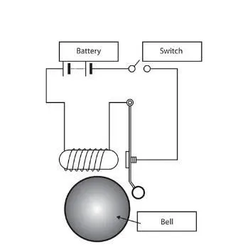
Simulink model of Doorbell using Solenoid
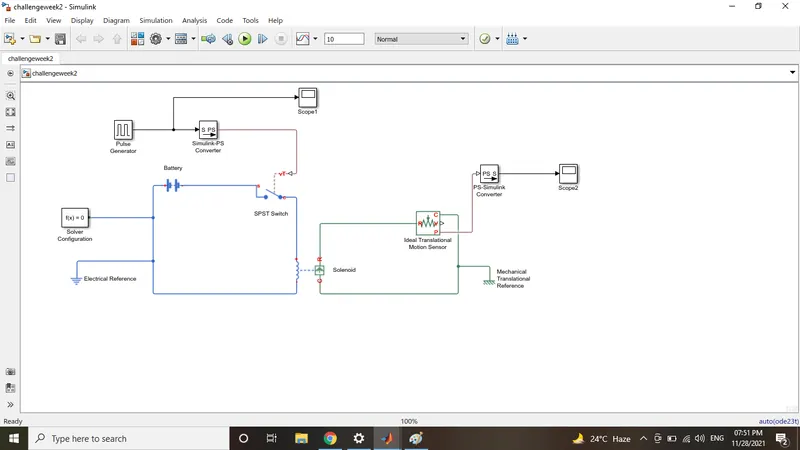
List of blocks used in following simulink model
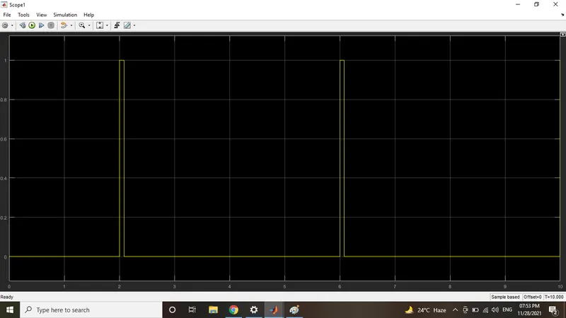
1)Pulse Generator: It is used to generates pulse wave at regualr intervels of time.
Given block parameters are Amplitude=1, Period=4, Pulse Width=2, Phase Delay=2
2)Simulink-Ps Converter: Converts simulink input signal into physical system input.
3)SP&ST Switch: SINGLE POLE SINGLE THROUGH Switch is controlled by external control signal.
4)Solver Configuration: Solver configuration block is defines solver parameters of block used to begin simulation.
5)Electrical Reference: Used as Electrical ground.
6)Battery: Battery is a constant voltage source at selected time. In this challenges i used infinite time.
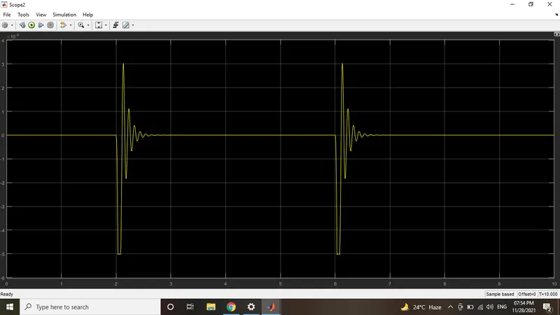
7)Solenoid: Solenoid is a coil which generates electromagnetic field leads to mechanical movement.
8)Ideal translational motion sensor: It represents the convertion of variable mechanical nodes into a control signal.
9)Mechanical Translational Reference: It represents the mechanical reference point with the ground.
10)PS-Simulink Converter: It converts the physical system parameters into unitless simulink values.
11)Scope: It displays the signal wavefroms with respect to the simulation time.
Input:
Output:
2. Aim: Use a thermistor to sense the temperature of a heater & turn on or turn off the fan as per the below conditions:
Temperature source: 20 °C from 0 to 10 seconds, 27 °C from 10 to 30 seconds, 23 °C from 30 to 50 seconds
Fan conditions: ON if the temperature above 25 °C, OFF otherwise
Simulink Model
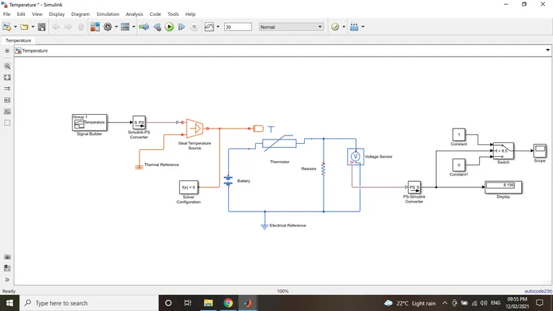
Step by Step Procedure of this model
1)Signal Builder: It is type of signal generater used to create different types of signals based on requirement
.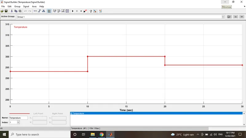
Above signal given as input to this model. Here input values provided in kelvins. At given conditions as shown in below table
| In celsius | In Kelvins | Given time in sec |
| 20 | 293 | 10 |
| 27 | 300 | 10 |
| 25 | 298 | 10 |
2)Simulink-PS Converter:Converts simulink input signal into physical system input.
3) Ideal Temperature Source: It is used to provide thermal energy at given temperature.
4)Solver Configuration: Solver configuration block is defines solver parameters of block used to begin simulation.
5)Battery: Battery is a constant voltage source at selected time. In this challenges i used infinite time.
6)Thermister: This is the type of variable resister changes with respective to thermal energy.
7)Resister: Which opposes the flow of current.
8)Voltage sensor: It is used to measure voltage across the +ve and -ve terminals.
9)Electrical Reference: It is used as electrical grounding.
10)PS-Simulink Converter: It converts physical system input to simulink input signal.
11)Switch: It acts as a Switch at thershold value.
12)Constant: It outputs the constant value given in contant parameters.
13)Scope: It shows the output of the simulink.
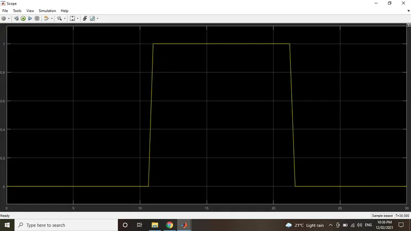
Above wavefrom shows the output of this model. As per the given conditions first 10s in off state at 20c(293k), second 10s in on state at 27c(300k) and third 10s in off state at 35c(298k).