Week-7 Challenge: DC Motor Control
1. A. Explain a MATLAB demo model named ‘Speed control of a DC motor using BJT H-bridge’.
B. Comment on the armature current shoot-up from the scope results.
C. Refer to the help section of ‘The Four-Quadrant Chopper DC Drive (DC7) block’. Compare it with the H-bridge model.
Solution:
A]Explain a MATLAB demo model named ‘Speed control of a DC motor using BJT H-bridge’.
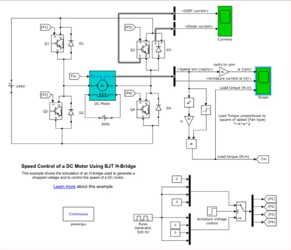
MATLAB demo model of "Speed control of a DC motor using BJT H-Bridge"
Working:
-In above model, input voltage is generated using a pulse generator.
-Block parameters of pulse generator is as shown in the below figure,
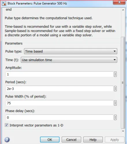
Amount of supply and duty cycle is assigned using a pulse generator.
- Pulse width = ON + OFF
- Duty Cycle = ON/(ON + OFF)
- D = (P x W)/T
-The switch block is connected to the pulse generator block through armature voltage control block.
-The H-Bridge consist of 4 BJT & Diode pairs (BJT simulated by IGBT models).
-Two transistor are switched simultaneously. i.e. Q1 & Q4 and Q2 & Q3.
- When Q1 and Q4 are fired;
A positive voltage is pplied to the motor.
And diodes 'D2 & D3' operated as a free wheeling diode, when Q1 and Q4 are off
- When Q2 and Q3 are fired;
A ngative voltage is applied to the motor.
And diodes 'D1 & D4' operates as a free wheeling diode,when Q2 & Q3 are switched off.
-A switchblock in the simulink model, splits the power supply into 4 parts. i.e. p1, p2, p3, & p4. These inputs are in "Goto From" block.
-Therefore these four types in inputs are connected to the transistor Q1, Q2, Q3, & Q4, through the "from" Block.
From block will recieve the signal from the "GotoBlock" with the specified tag.
- Switches
Q1 and Q2 ---> Forward Motoring.
Q2 and Q3 ---> Reverse Motoring.
-This formation is called as an H-Bridge, an H-Bridge is an arangement of transistor that allows a circuit full control over a standard electric DC motor.
-DC motor is connected to battery and the mechanical input of DC motor is initiatd as a torque.
-Load torque proportional to square of a speed. i.e. T = k.ω^2
where;
ω = speed
T = Load Torque
-Torque for mechanicl input of DC motor also switched by Goto & From block.
-The output of DC motor is connected with "BUS sector"
-The conversion of speed from rad/sec to rpm is done between BUS sector & scope using converter block.
-The speed is plotted in a scope.
B. Comment on the armature current shoot-up from the scope results.
Output:
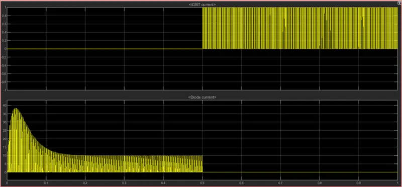
- In the above graph, IGBT current and Diode current is passed through Quadrant Q3 & D3 is shown.
- Q3 represents the IGBT current and D3 represents the Diode current.
- During 0.5 sec, D3 switch is ON (given according to the pulse generator). After 0.5 sec, D3 is OFF and IGBT current starts flowing while Q3 remains ON.
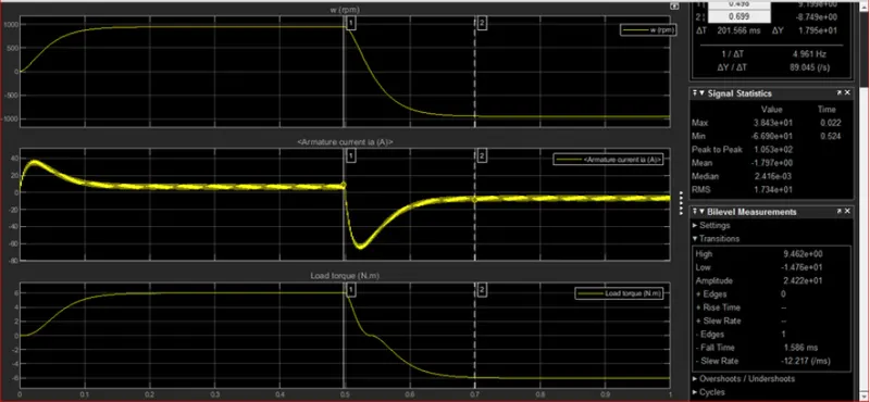
- The speed and armature current is obtained b the DC motor and Load torque is calculated by load torque proportional to the square of a speed.
- At starting, a sudden rise or shootup can be seen.
- The above graph shows that the speed is increased in certain period of time and at that time armature current is positive whereas load Torque also moves forward.
- After 0.5 sec, a sudden rise acn be seen and speed gets decreased, in that time armature current is negative terminal whereas Torque act as reverse action.
- Here a sudden rise appears while Armature current is processed at a positive and negative terminal.
C. Refer to the help section of ‘The Four-Quadrant Chopper DC Drive (DC7) block’. Compare it with the H-bridge model.
Simulink model of DC7 Four quadrant Chopper DC drive:
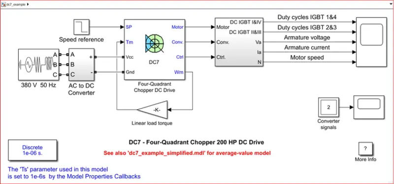
- A 200HP Dc motor is seperately excited with a constant 150V DC field voltage source.
- The armature voltage is provided by an IGBT converter controlled by two PI regulators
- The converter is fed by a 515V DC obtained by the rectification of 380V AC source.
- A braking chopper has been used in order to limit the DC bus voltage.
- First regulator is a speed regulator followed by the current regulator.
- The speed reference change rate follows acceleration and deceleration ramps in order to avoid sudden reference chnges that could cause armature over current and destabilize the system.
- The curent regulatory controls the armature current.
- For proper system behavior, the instantaneous pulse valuse of IGBT devices 1 & 4 are opposite to the IGBT devices 2 & 3.
- This generates the average armture voltage needed to obtain the desired armature current. In order to limit the ampliture of the current oscillations, a smoothing inductance is placed in series with te armature circuit.
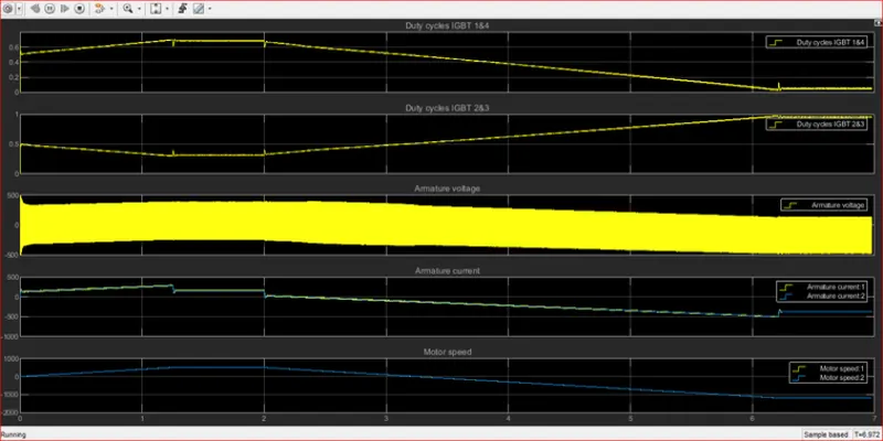
Output:
DC7 V/S H-Bridge:
| Sr No. | BJT H-Bridge Drive | Four Quadrant Chopper Drive |
| 1 | It is used for changing the direction of the motor.(forward and reverse) | The motor can be operated in 4 different modes.(Forward motoring & Braking and Reverse motoring & Braking) |
| 2 | Regenarative Braking is not possible. | Regenerative braking can be achieved. |
| 3 | The source is of Fixed DC supply. | The source is an AC supply which can be rectified to DC varying supply. |
| 4 | The motor speed reference cannot be fed | The motor speed reference can be fed |
| 5 | The armatue current shoots up during the phase transition. | The armature current doesn't shootup to a value of BJT H-Bridge but for low voltage value it's negligible. |
| 6 | Less vehicle control. | Good vehicle control |
| 7 | Continous signals | Signals are not continous and are discrete. |
2. Develop a 2-quadrant chopper using simulink & explain the working of the same with the relevant results. (Refer to article - Multiquadrant operation of motor )
Solution:
Simulink model:
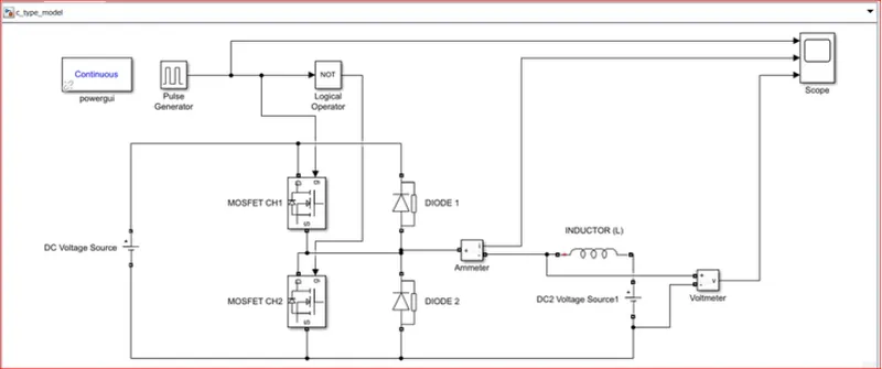
Blocks used:
- Power GUI
- Voltage measurement
- Curent mesurement
- Dc voltage source
- MOSFET
- Pulse generator
- Diode
- Series RLC band
- Logical operator
--> All the blocks are arrenged as shown in the simulink model.
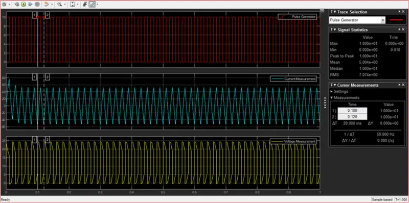
Output:
Two Quadrant chopper:
Type A chopper or Type C chopper.
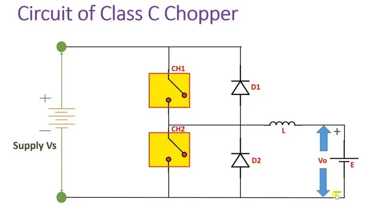
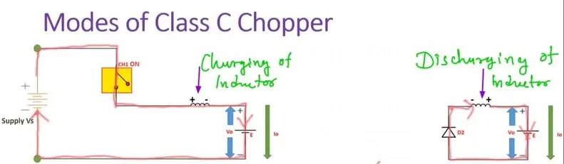
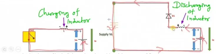
Charging and discharging modes of Type C chopper:
Working of Class C Chopper:
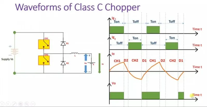
- The sequence of Ig1 and Ig2 shows how we trigger CH1 with Ig1 and CH2 with Ig2 current.
- As seen in the above figure, we trigger Ig1 means CH1 switch will close and current will flow from Vs to CH1 to Inductor to E to Back to Vs.
- while in this process the inductor will charge by (+ -) polarity.
- Direction of current can be seen positively increasing.
- When CH1 is ON supply voltage will appear at output voltage and when diode D1 is ON supply appear to output voltage is Vs, the supply voltage Vs will be appearing while CH1 ON and Diode D1 ON in output.
3. Explain in a brief about operation of BLDC motor.
Solution:
Operation of BLDC motor:
What id Brushless DC motor?
-Brushless DC electric motors also known as electronically commutated motors (ECMs, EC motors).
-Primary efficiency is a most importent feature for BLDC motors. Because the rotor is the sole bearer of the magnets and it doesn't require any power. i.e. no connections, no commutator and no brushes.
-In place of these, the motor employs control circuitry. To detect where the rotor is at certain times, BLDC motors employ along with controllers, rotary encoders or a Hall sensor.
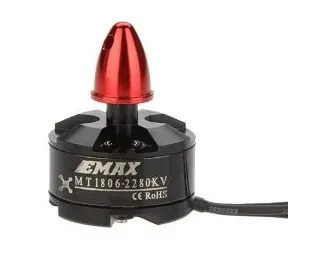
Construction of BLDC motor:
-In this motor, the permanent magnets attach to the rotor. The current-carrying conductors or armature windings are located on the stator. They use electrical commutation to convert electrical energy into mechanical energy.
-The main design difference between a brushed and brushless motors is the replacement of mechanical commutator with an electric switch circuit. A BLDC Motor is a type of synchronous motor in the sense that the magnetic field generated by the stator and the rotor revolve at the same frequency.
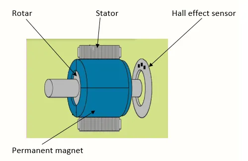
-Brushless motor does not have any current carrying commutators. The field inside a brushless motor is switched through an amplifier which is triggered by the commutating device like an optical encoder.
-The layout of a DC brushless motor can vary depending on whether it is in “Out runner” style or “Inrunner” style.
-
Outrunner – The field magnet is a drum rotor which rotates around the stator. This style is preferred for applications that require high torque and where high rpm isn’t a requirement.
-
In runner – The stator is a fixed drum in which the field magnet rotates. This motor is known for producing less torque than the out runner style, but is capable of spinning at very high rpm.
Working Principle of BLDC motor:
-BLDC motor works on the principle similar to that of a Brushed dc motor. The Lorentz force law which states that whenever a current carrying conductor placed in a magnetic field it experiences a force. As a consequence of reaction force, the magnet will experience an equal and opposite force. In the BLDC motor, the current carrying conductor is stationary and the permanent magnet is moving.
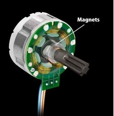
-When the stator coils get a supply from source, it becomes electromagnet and starts producing the uniform field in the air gap. Though the source of supply is DC, switching makes to generate an AC voltage waveform with trapezoidal shape. Due to the force of interaction between electromagnet stator and permanent magnet rotor, the rotor continues to rotate.
-With the switching of windings as High and Low signals, corresponding winding energized as North and South poles. The permanent magnet rotor with North and South poles align with stator poles which causes the motor to rotate.
Advantages:
- Less overall maintenance due to absence of brushes
- Reduced size with far superior thermal characteristics
- Higher speed range and lower electric noise generation.
- It has no mechanical commutator and associated problems
- High efficiency and high output power to size ratio due to the use of permanent magnet rotor
- High speed of operation even in loaded and unloaded conditions due to the absence of brushes that limits the speed
- Smaller motor geometry and lighter in weight than both brushed type DC and induction AC motors.
- Long life as no inspection and maintenance is required for commutator system
- Higher dynamic response due to low inertia and carrying windings in the stator
- Less electromagnetic interference
- Low noise due to absence of brushes
Limitations:
- These motors are costly
- Electronic controller required control this motor is expensive
- Requires complex drive circuitry
- Need of additional sensors
Applications:
Brushless DC motors (BLDC) use for a wide variety of application requirements such as varying loads, constant loads and positioning applications in the fields of industrial control, automotive, aviation, automation systems, health care equipments etc.
- Computer hard drives and DVD/CD players
- Electric vehicles, hybrid vehicles, and electric bicycles
- Industrial robots, CNC machine tools, and simple belt driven systems
- Washing machines, compressors and dryers
- Fans, pumps and blowers.