Week-7 Challenge: DC Motor Control
1. A. MATLAB demo model ‘Speed control of a DC motor using BJT H-bridge’: Model Link
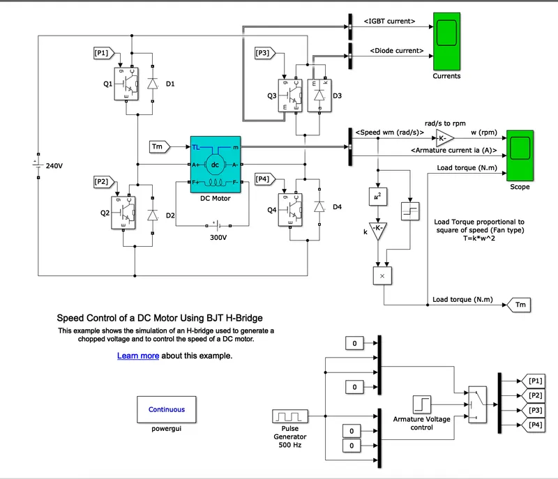
BJT H-bridge used to generate a chopped voltage and to control the speed of a DC motor.
Description:
- Pulse Width Modulation (PWM) is a popular technique used to control the speed of a DC motor by controlling the duty cycle of the driving voltage of the switches.The speed of the motor can be easily controlled by vary-ing the duty cycle of the PWM signal and is directly proportional to the duty cycle that is greater the duty cycle, the greater will be the speed of the motor.
- With the help of Pulse generator, Mux,DeMux and switches; Gate voltages(P1,P2,P3 and P4) are generated. These voltages are given to gate terminal of IGBTs (Q1,Q2,Q3 and Q4).
- The H-bridge consists of four BJT/Diode pairs (BJT simulated by IGBT models). Two transistors are switched simultaneously: Q1 and Q4 or Q2 and Q3.
- When Q1 and Q4 are fired, a positive voltage is applied to the motor and diodes D2-D3 operate as free-wheeling diodes when Q1 and Q4 are switched off.
- When Q2 and Q3 are fired, a negative voltage is applied to the motor and diodes D1-D4 operate as free-wheeling diodes when Q2 and Q3 are switched off.
- Output of DC motor is armature current (A) and speed (rad/s), it is converted into rpm.
- Speed is converted into Torque(Nm) by using K*w^2 and this torque goes back to DC motor as feedback.
Simulation:
- The motor starts in the positive direction with a duty cycle of 75% (mean DC voltage of 180V).
- At t= 0.5 sec., the armature voltage is suddenly reversed and the motor runs in the negative direction.
- 'Scope' shows motor speed, armature current and load torque and 'Currents' shows currents flowing inBJT Q3 and diode D3.
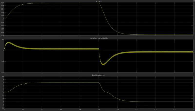
- As motor changes its direction from forward to reverse, there is shoot in armature current.
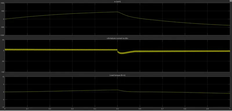
- This shoot can be decreased by decreasing duty cycle.
- Here duty cycle reduced from 75% to 50%
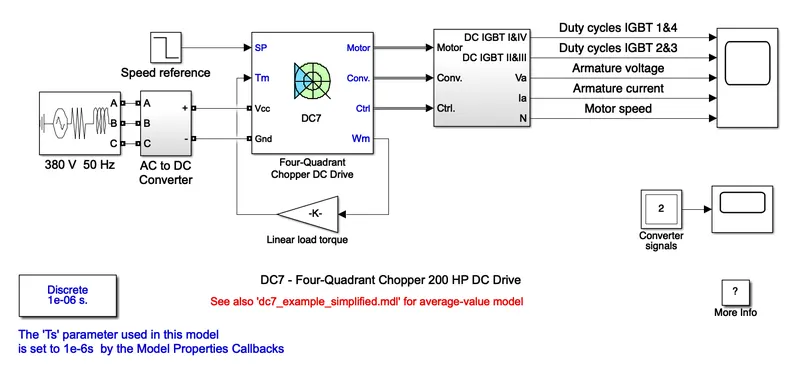
- The armature voltage is provided by an IGBT converter controlled by two PI regulators.The first regulator is a speed regulator, followed by a current regulator. The speed regulator outputs the armature current reference (in p.u.) used bythe current controller in order to obtain the electromagnetic torque needed to reach the desired speed.
- The speed reference change rate follows acceleration and deceleration ramps in order to avoid sudden reference changes that could cause armature over-current and destabilize the system.
- The current regulator controls the armature current by computing the appropriate duty ratios of the 5 kHz pulses of the four IGBT devices (Pulse Width Modulation).
- For proper system behaviour, the instantaneous pulse values of IGBT devices 1 and 4 are opposite to those of IGBT devices 2 and 3. This generates the average armature voltage needed to obtain the desired armature current.
- wm is converted into Tm and works as feedback in Four-quadrant Chopper DC drive.
Simulation:
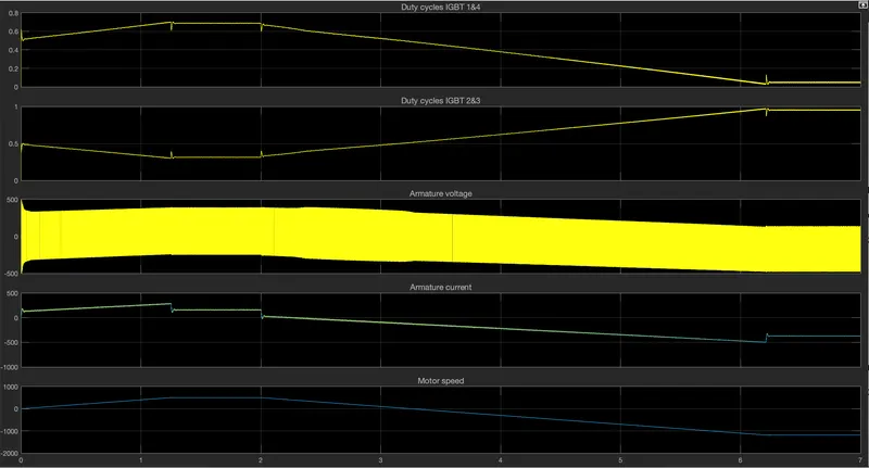
- The motor is coupled to a linear load, which means that the mechanical torque of the load is proportional to the speed.
- The speed reference is set at 500 rpm at t = 0 s. Observe that the motor speed follows the reference ramp accurately (+400 rpm/s) and reaches steady state around t = 1.3 s.
- The armature current follows the current reference very well, with fast response time and small ripples. Notice that the current ripple frequency is 5 kHz.
- At t = 2 s, speed reference drops to -1184 rpm. The current reference decreases to reduce the electromagnetic torque and causes the motor to decelerate with the help of the load torque.
- At t = 2.2 s, the current reverses in order to produce a braking electromagnetic torque (dynamic braking mode). This causes the DC bus voltage to increase.
- At t = 3.25 s, the motor reaches 0 rpm and the load torque reverses and becomes negative. The negative current now produces an accelerating electromagnetic torque to allow the motor to follow the negative speed ramp (-400 rpm/s). At t = 6.3 s, the speed reaches -1184 rpm and stabilizes around its reference.
Comparison of BJT H-bridge and Four quadrant chopper DC7:
|
BJT H bridge |
Four Quadrant DC7 chopper |
|
Current shoots |
Armature current have fast response time and small ripples. |
|
No regenerative braking |
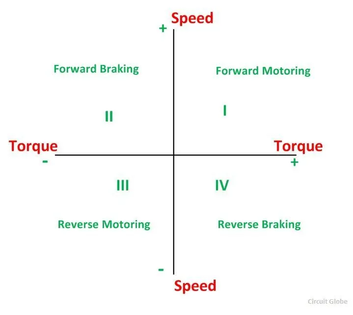
Regenerative Braking possible |
3. Two-quadrant chopper using simulink:
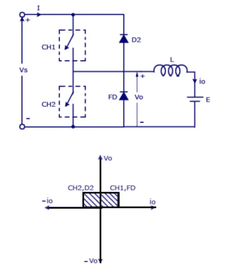
In 2-quad chopper, the average voltage will be always positive but the average load current might be positive or negative. The two switches CH1 and CH2 should not be turned on simultaneously as the combined action may cause a short circuit in supply lines. For regenerative braking and motoring these types of chopper configuration is used.
we always gets a positive output voltage Vo as the freewheeling diode FD is present across the load. when the copper CH1 is on the current flows from source to load. The inductor stores energy. when Ch1 turn OFF the freewheeling diode starts conducting and the output voltage Vo will be equal to Vs. The direction of load current io will be reversed. The current io will be flowing towards the source. The load current will be negative when the CH2 is on. The current completes its path through diode D2.
Circuit-Diagram:
Model:
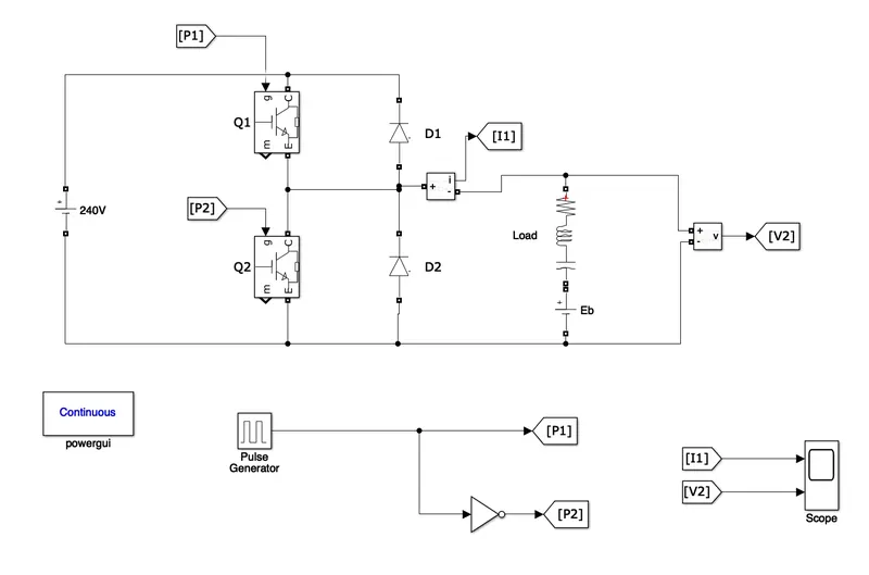
- For switching action, IGBTs are used. Here D2 is free wheeling diode. Pulse generator is used with 50% duty cycle. For alternative action of two IGBTs, NOT logic is used.
- Model is made as per circuit diagram.
Simulation:
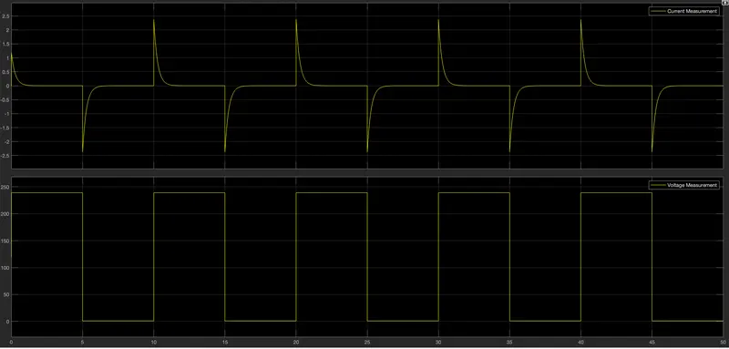
- current is positive when Q1 is ON and D2 is conducting.
- current is negative when Q2 is ON and D1 is conducting.
4. BLDC motor:
Brushless DC electric motors also known as electronically commutated motors (ECMs, EC motors).
Primary efficiency is a most importent feature for BLDC motors. Because the rotor is the sole bearer of the magnets and it doesn't require any power. i.e. no connections, no commutator and no brushes. In place of these, the motor employs control circuitry. To detect where the rotor is at certain times, BLDC motors employ along with controllers, rotary encoders or a Hall sensor.
Construction:
In this motor, the permanent magnets attach to the rotor. The current-carrying conductors or armature windings are located on the stator. They use electrical commutation to convert electrical energy into mechanical energy.
The main design difference between a brushed and brushless motors is the replacement of mechanical commutator with an electric switch circuit. A BLDC Motor is a type of synchronous motor in the sense that the magnetic field generated by the stator and the rotor revolve at the same frequency.
Brushless motor does not have any current carrying cummutators. The field inside a brushless motor is switched through an amplifier which is triggered by the commutating device like an optical encoder.
The layout of a DC brushless motor can vary depending on whether it is in “Out runner” style or “Inrunner” style.
-
Outrunner – The field magnet is a drum rotor which rotates around the stator. This style is preferred for applications that require high torque and where high rpm isn’t a requirement.
-
In runner – The stator is a fixed drum in which the field magnet rotates. This motor is known for producing less torque than the out runner style, but is capable of spinning at very high rpm.
Working Principle:
BLDC motor works on the principle similar to that of a Brushed DC motor. The Lorentz force law which states that whenever a current carrying conductor placed in a magnetic field it experiences a force. As a consequence of reaction force, the magnet will experience an equal and opposite force. In the BLDC motor, the current carrying conductor is stationary and the permanent magnet is moving.
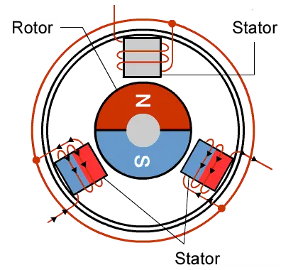
When the stator coils get a supply from source, it becomes electromagnet and starts producing the uniform field in the air gap. Though the source of supply is DC, switching makes to generate an AC voltage waveform with trapezoidal shape. Due to the force of interaction between electromagnet stator and permanent magnet rotor, the rotor continues to rotate.
With the switching of windings as High and Low signals, corresponding winding energized as North and South poles. The permanent magnet rotor with North and South poles align with stator poles which causes the motor to rotate
Advantages:
- Less overall maintenance due to absence of brushes
- Reduced size with far superior thermal characteristics
- Higher speed range and lower electric noise generation.
- It has no mechanical commutator and associated problems
- High efficiency and high output power to size ratio due to the use of permanent magnet rotor
- High speed of operation even in loaded and unloaded conditions due to the absence of brushes that limits the speed
- Smaller motor geometry and lighter in weight than both brushed type DC and induction AC motors.
- Long life as no inspection and maintenance is required for commutator system
- Higher dynamic response due to low inertia and carrying windings in the stator
- Less electromagnetic interference
- Low noise due to absence of brushes
Limitations:
- These motors are costly
- Electronic controller required control this motor is expensive
- Requires complex drive circuitry
- Need of additional sensors
Applications:
Brushless DC motors (BLDC) use for a wide variety of application requirements such as varying loads, constant loads and positioning applications in the fields of industrial control, automotive, aviation, automation systems, health care equipments etc.
- Electric vehicles, hybrid vehicles, and electric bicycles
- Industrial robots, CNC machine tools, and simple belt driven systems
- Washing machines, compressors and dryers
- Fans, pumps and blowers.