Week-7 Challenge: DC Motor Control
1. Run MATLAB demo ‘Speed control of a DC motor using BJT H-bridge’. Modify the model such that the armature current doesn’t shoot up when the motor changes direction from forward to reverse.
Major blocks used
1. IGBT
The Bipolar Junction Transistor (BJT) when used for power switching applications, operates as an IGBT. When it is conducting, that is, when BJT operating in the saturated region, a forward voltage is developed between collector and emitter (in the range of 1 V). Therefore, the IGBT block can be used to model the BJT device. There are 4 IGBT blocks used.
2.Diode
Each of the 4 IGBT blocks is connected with a diode in parallel. The application of the diode is to freewheel the reverse current produced. Hence this diode protects the IGBT from the reverse voltage.
3.DC Machine
A 5HP,240V,1750RPM DC Machine is selected for the simulation. The mechanical input is chosen as Torque and the field type is selected as Wound.
4.DC Voltage Sources
There are two DC voltage sources used here. A 300V source is given as the field voltage for the DC machine and the 240V is the main source that is connected to the terminals of IGBTs.
The H-bridge consists of four BJT/Diode pairs (BJT simulated by IGBT models). Two transistors are switched simultaneously: Quadrant 1(Q1) and Quadrant 4(Q4) or Quadrant 2(Q2) and Quadrant 3(Q3). When Q1 and Q4 are fired, a positive voltage is applied to the motor, and diodes D2-D3 operate as free-wheeling diodes when Q1 and Q4 are switched off. When Q2 and Q3 are fired, a negative voltage is applied to the motor, and diodes D1-D4 operate as free-wheeling diodes when Q2 and Q3 are switched off.
Given below is the Matlab simulation diagram
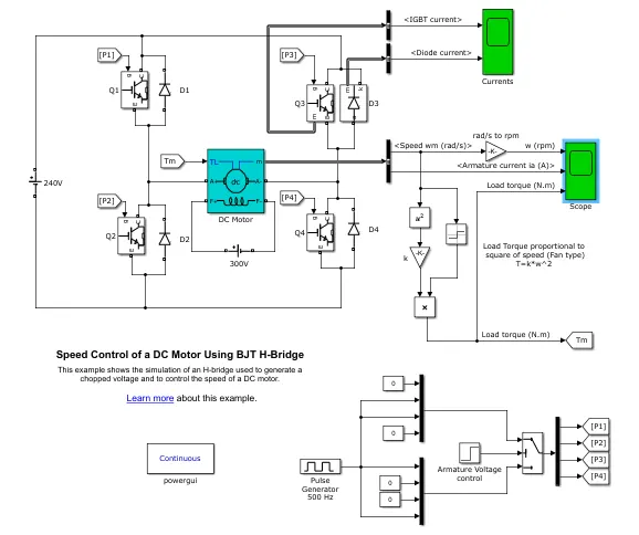
The motor starts in a positive direction with a duty cycle of 75% (mean DC voltage of 180V). At t= 0.5 sec., the armature voltage is suddenly reversed and the motor runs in a negative direction. The total simulation time is 1 sec.
'Scope' shows motor speed, armature current, and load torque and 'Currents' shows currents flowing in BJT Q3 and diode D3.
1. 'Scope' output
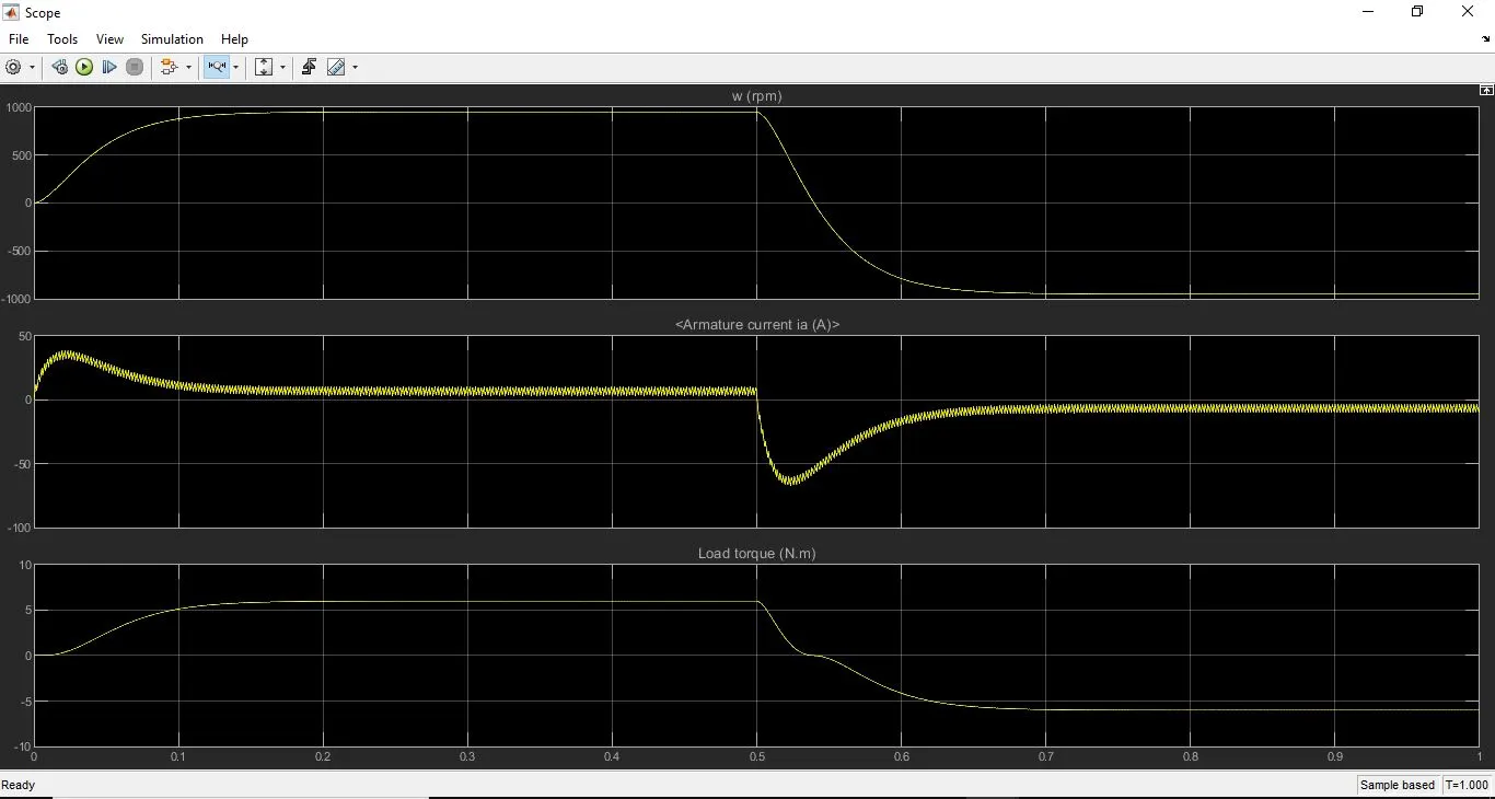
Here we can see the motor speed(rpm) output in the first graph,
The motor speed increases from 0 to 1000 rpm in nearly 0.2sec and it is maintained till 0.5 sec, then, when the direction is changed the motor speed changes from 1000 rpm to -1000 rpm in the next 0.2 secs and it is maintained
Armature Current(A) is shown in the second graph
Armature Current rises to a higher value of nearly 40A at the start and then settles down to lower values. Then, when, the direction is reversed it shows a sudden spike of current with a maximum value greater than -50A. Armature current has small distortions like saw tooth waveform when observed closely.
Load Torque(Nm) is shown in the third graph
Initially, Load torque increases from 0 to 6 Nm and maintains for 0.5sec. When the direction reversed, the Load torque reduces from 6 to 0 and holds for a very little time(<0.01sec) and decreases to -6Nm, the maintains it until the end of the simulation.
2. 'Currents' output
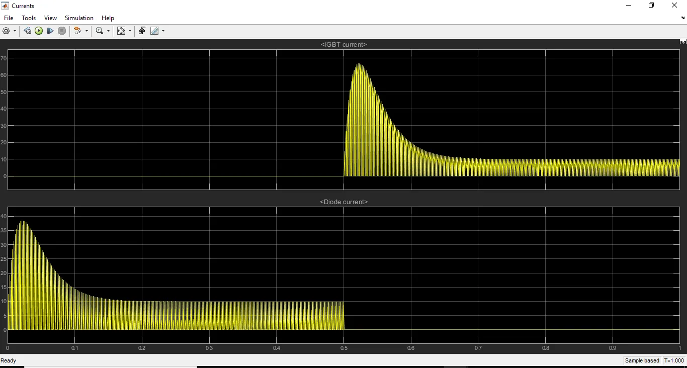
Here the IGBT current and the Diode current of IGBT Q3 and diode D3 are shown.
We can see that the IGBT current is only present when the direction of the motor is reversed and the Diode current is only present when the direction is the first direction. This shows the freewheel effect of the diode.
The IGBT current is zero at the start and it increases to nearly 70A after the reversal of the motor direction then settles down to a lower value
The Diode current increases to nearly 40A at the start of the motor and settles down to a lower value and maintain with distortions till 0.5sec. Then becomes zero.
Both the currents have slight distortions when observed closely.
To modify the model such that the armature current doesn’t shoot up when the motor changes direction from forward to reverse we can change the duty ratio.
By changing the duty ratio DC voltage changes.
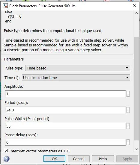
Here we change the duty ratio from 75% to 45%
55% of the duty ratio means DC voltage is 0.45*240=108V
Let us look into the change in output
1.'Scope' Output
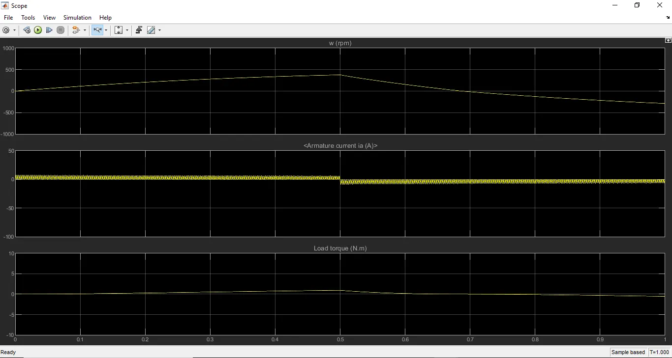
Here the Speed increases from 0 to nearly 500rpm and reduces to nearly -500rpm after the reversal of direction. All the changes occur gradually.
In the second plot, We can observe that the armature current there is very less distortion when the motor direction changes from forward to reverse.
We can observe the same here in the below figure.
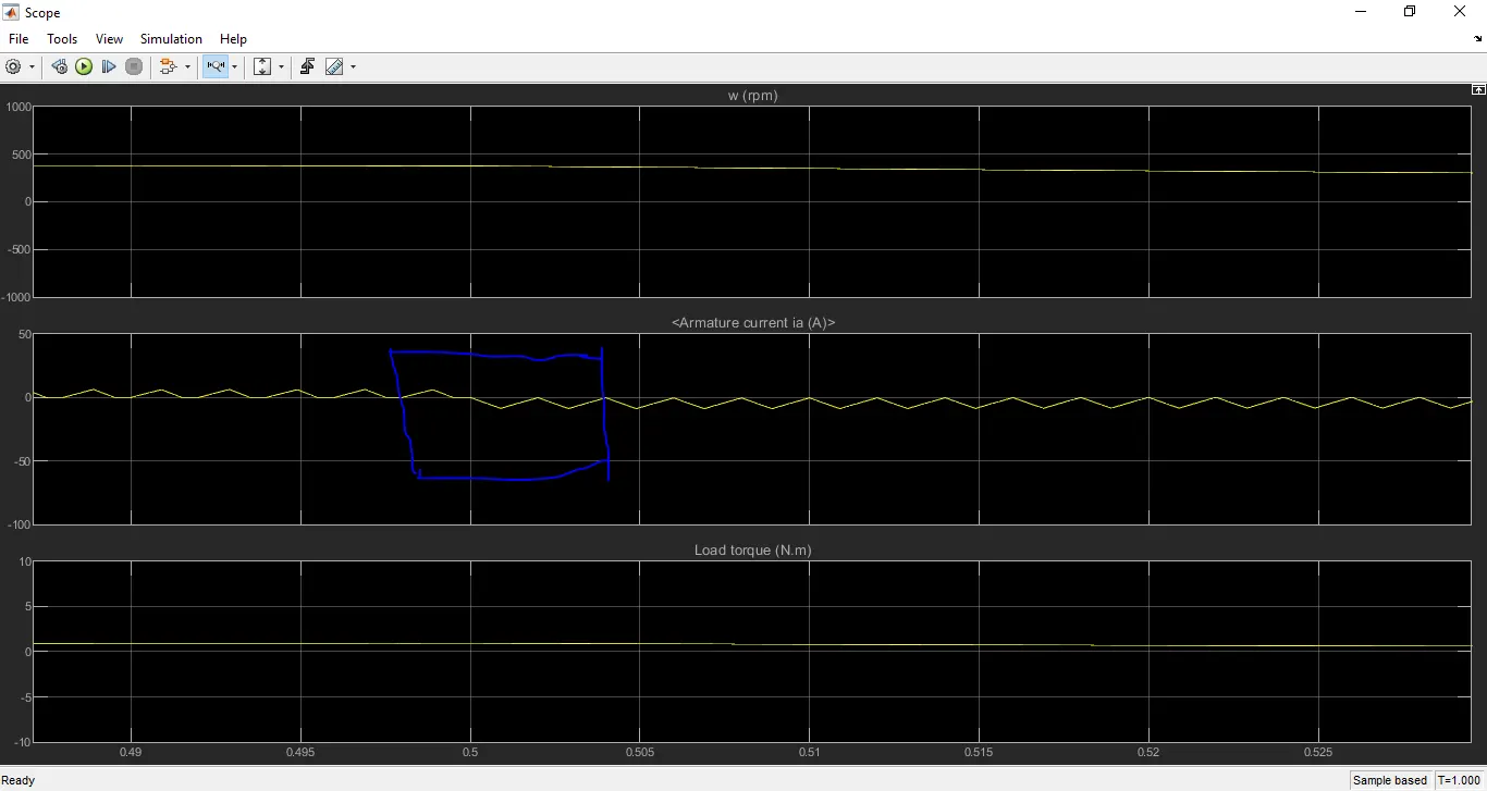
The load torque also reduces compared to the previous model.
2. 'Currents' Output
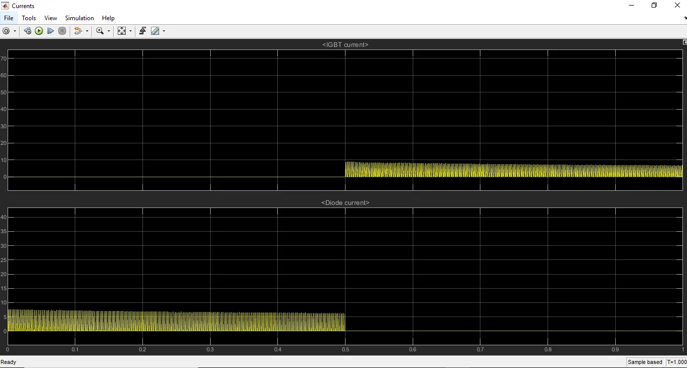
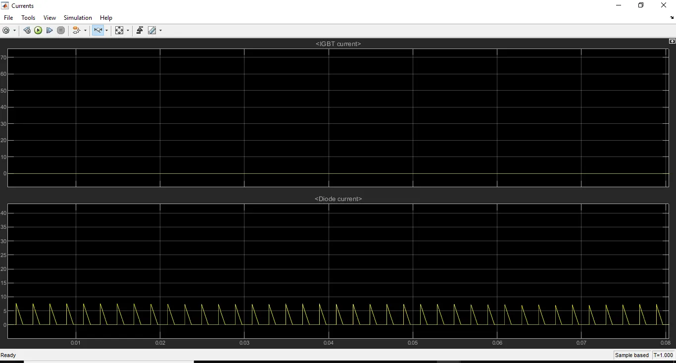
The initial peak in the Diode current and the peak current of the IGBT current after reversal of motor direction, both reduces here. We can observe the output like a sawtooth waveform for both the graphs.
A close observation of the IGBT graph is given below which shows a 10A peak current
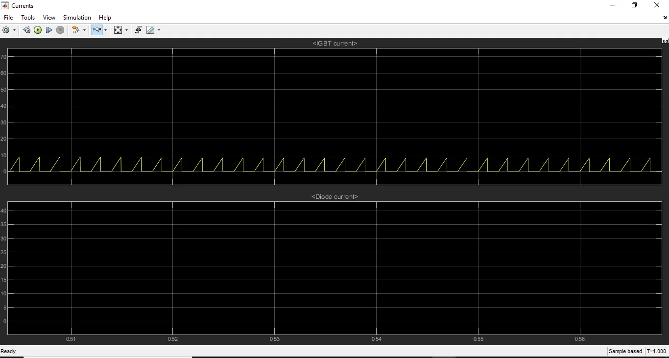
A close observation of the Diode current is given below which shows 7A peak current.
2. Refer to the help section of ‘The Four-Quadrant Chopper DC Drive (DC7) block’. Compare it with the H-bridge model.
** The Four-Quadrant Chopper DC Drive (DC7) block is shown below
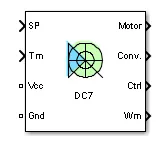
A short description of the Block Inputs and Outputs taken from the Matlab Help is given below.
SP
The speed or torque set point. We can connect varying speed inputs to this terminal. That may be a drive cycle or any signal.
Tm
The mechanical input: load torque (Tm)
Vcc, Gnd
The DC voltage source electric connections. The voltage must be adequate for the motor size.
Wm
The mechanical output: motor speed (Wm)
When the Output bus mode parameter is set to Multiple output buses, the block has the following three output buses
Motor
The motor measurement vector. This vector is composed of two elements:
The armature voltage
The DC motor measurement vector (containing the speed, armature current, field current, and electromagnetic torque values). Note that the speed signal is converted from rad/s to rpm before output.
Conv
The IGBT/Diode device measurement vector. This vector includes the converter output voltage. The output current is not included since it is equal to the DC motor armature current. Note that all current and voltage values of the converter can be visualized with the Multimeter block.
Ctrl
The controller measurement vector. This vector contains:
The armature current reference
The duty cycle of the PWM pulses
The speed or torque error (the difference between the speed reference ramp and actual speed or between the torque reference and actual torque)
The speed reference ramp or torque reference
Block Description
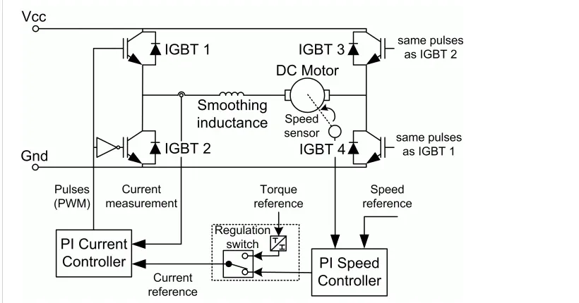
The Four-Quadrant Chopper DC Drive (DC7) block represents a four-quadrant, DC-supplied, chopper (or DC-DC PWM converter) drive for DC motors. This drive features closed-loop speed control with the four-quadrant operation. The speed control loop outputs the reference armature current of the machine. Using a PI current controller, the chopper duty cycle corresponding to the commanded armature current is derived. This duty cycle is then compared with a sawtooth carrier signal to obtain the required PWM signals for the chopper.
The internal diagram is given below.
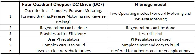
Comparison between Four-Quadrant Chopper DC Drive(DC7) and H-Bridge Model is given below
3. Make a suitable EV model using the DC7 block and make a result report.
To simulate an EV model using DC7 block we must add a drive cycle and vehicle torque, into the input ports of the DC7 block.
The output from the DC7 block is given to the Motor, and the Converter and Control ports are connected as such.
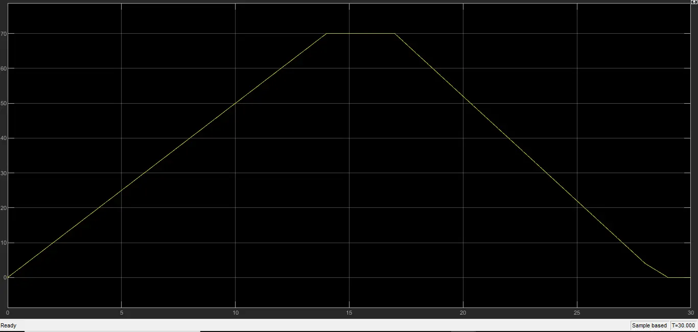
The drive cycle used is a manual drive cycle, uploaded in an Excel file(File Attached:MyDriveCycle.xlsx)
The simulation time is set to 30sec as in DriveCycle.
The drive cycle is shown below.
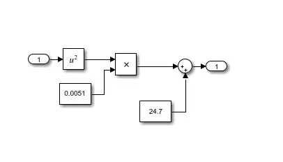
The vehicle torque equation is taken as
T=0.0051`omega^2`+24.7
This equation is implemented into a subsystem "Vehicle Load Torque" as shown below
The Diagram is given below.
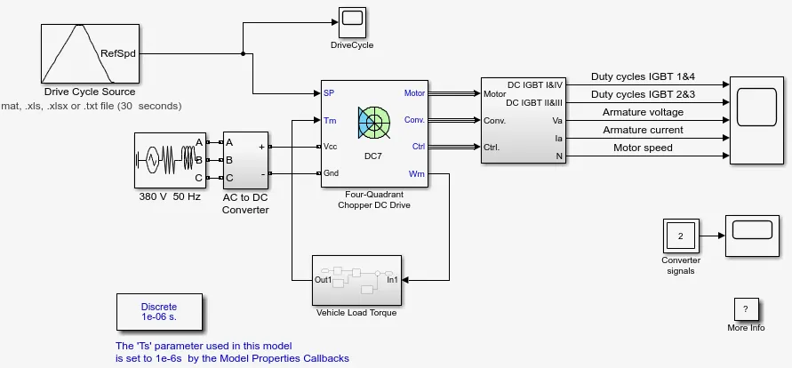
The Outputs taken are Duty Cycles of IGBT 1&3 and IGBT 2&4, Armature voltage, Armature current, and Motor speed.
The output is observed in the figure below.
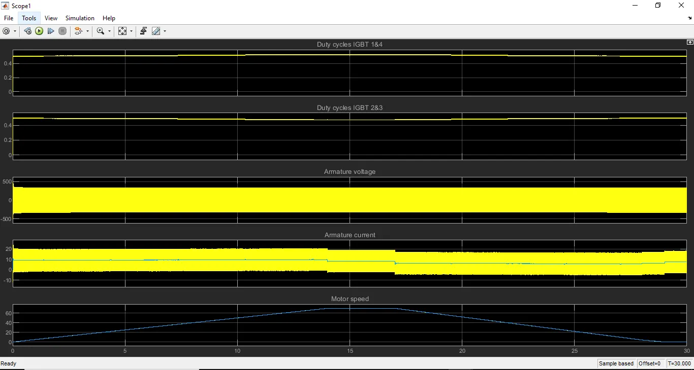
The first and second plots show the IGBT duty cycles. Here we can see that one duty cycle is exactly opposite to the other. It is also observed that the value greater than 0.5 and less than 0.5. The close view plots can be analyzed from the below figure.

The third plot shows the armature voltage value, which shifts between 380V and -380V
The plot can be closely observed from the figure below.

The Forth plot shows the armature current value, the peak can be observed as 20A
The plot can be closely observed from the figure below.

The Fifth plot shows the Motor speed, It is similar to the DriveCycle provided.
The plot can be closely observed from the figure below.

CONCLUSION
- The ‘Speed control of a DC motor using BJT H-bridge’. model is simulated and it is modified such that the armature current doesn’t shoot up when the motor changes direction from forward to reverse by reducing the Duty Ratio. The results are explained.
- ‘The Four-Quadrant Chopper DC Drive (DC7) block’ is explained and it is compared with the H-bridge model.
- An EV model using DC7 block is made and results are described.