Week-7 Challenge: DC Motor Control
1. A. Explain a MATLAB demo model named ‘Speed control of a DC motor using BJT H-bridge’.
B. Comment on the armature current shoot-up from the scope results.
C. Refer to the help section of ‘The Four-Quadrant Chopper DC Drive (DC7) block’. Compare it with the H-bridge model.
Speed Control of a DC motor using BJT Bridge;
Usage of motor is different as per the needs and the speed varies acoording to the usages. At the early stage, We have AC and motor which have the fixed speed(rotation per minute).
The motor manufacturers, design their motor for particular RPM for particular application.
But in later years, due to the technological innovations, there is new era of drives come into action for changing the speed of the motor to the presize manner and with high efficiency.
With the help of the Transistors, the waves of the Alternating currents Voltages are sculptured into the desired voltage to control the speed .
PWM Technique plays a major role in converting the fixed voltage into desired output voltage in order to get the different speed of the motor.
DC motors are converting DC energy into Mechanical energy.
In order control the speed, there are three methods available.Firstly the equation given as,
The speed of a DC motor (N) is equal to:
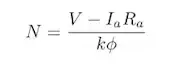
Which means , Speed is directly proportinal to Voltage V,Resistance Ra and phi which is flux per pole.
If the resistance control method and flux change is applied, there is lot of losses occurs . So, we perfer to change the voltage to control the speed.
The Block model is :
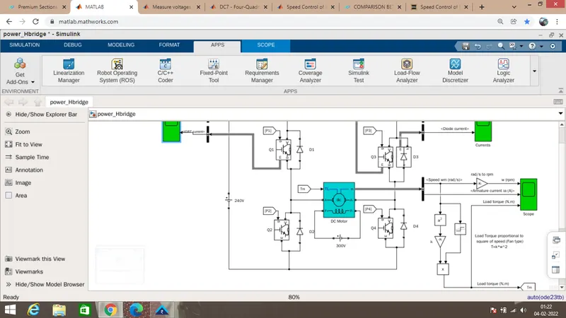
The Model comprises of
1.Battery Voltage Source,
2. 4 BJT Transistors,
3. 4 Diodes
4.DC motor
5.Pulse Generator
These are the major Blocks.
Battery Source voltage is the DC battery supply of 240V and 300V
In DC Motor, there are armature windings and the field. we have given constant 300 V supply to the Field and the armature voltage is modulated to achieve the desired speed in EV vehicle.
BJT is Bipolar Junction Transistor which has the terminals of Base Collector Emitter.
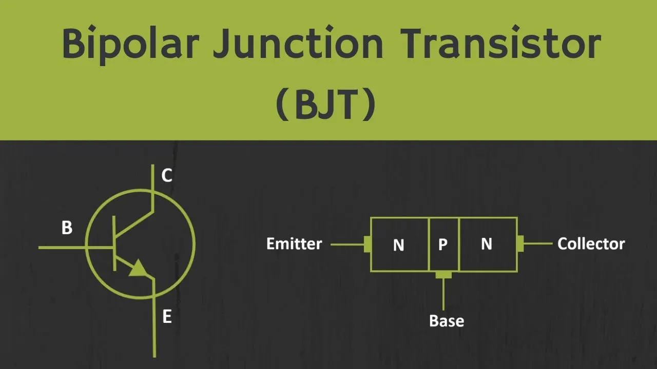
A Bipolar junction transistor, shortly termed as BJT is called so as it has two PN junctions for its function. This BJT is nothing but a normal transistor. It has got two types of configurations PNP and NPN. In this Model, wehave used NPN Transistor.
In this BJT,Collector and Emitter is a path which is triggered by the Base. BJT works only when there is a supply on Base Emitter Region.
when the signal is given through the Pulse Width Generator, the base signal triggers accordingly to allow the voltage to the desired level.
Diodes.
Diodes are nothing but the one way to allow the voltage . It blocks the current, when it flows through the opposite direction. In precisely, Its a one way to passs through.
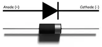
Current can flow through Anode to Cathode only.
Motor:
Dc motor is connected to the arm of the Transistors. So that the speed varies according to the voltages. Torque value is given to the motor.
Pulse Generator.
It plays a major role in controlling the voltage . According to thge duty cycle, The pulse genrator ,generates the pulses. So that the 240 V is pulsated to the desired value.
Working Principle of the Model.
There are 4 Transistors and 4 Diodes in the H bridge. Q1 Q2 Q3 Q4 are the 4 transistors and D1 D2 D3 D4 are the 4 diodes.Q1 Q2 are one arm and Q3 Q4 are another arm in H bridge.
Now We are going to Trigger Q1 and Q2. What will happen?
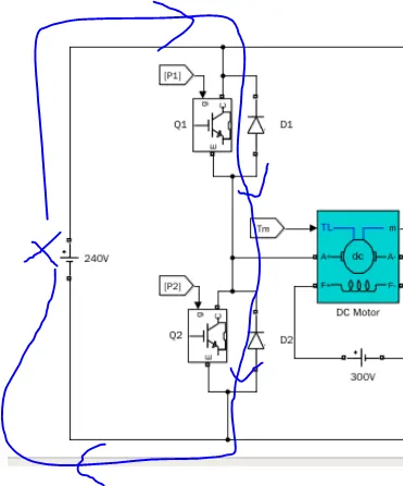
The positive and the negative terminals get short and the short circuit happens. So, In order to do the operation, we have to know the Quadrant operation of H bridge.
Quadrant
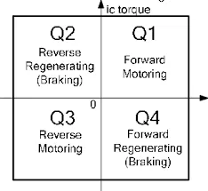
There are 4 quadrants of operation :
1. Forward Motoring
2. Forward Regenerating
3.Reverse Motoring
4.Reverse Regenarating
In H bridge, only 2 Quadrant is possible.
1. Forward Motoring
2.Reverse Motoring
We can start the simulation .
When Triggering Q1 and Q4 , at the first sampling time, the motor Rotates in the Forward Direction , Tends to Positive speed and Positive Torque.
Q1 and Q 4 triggering
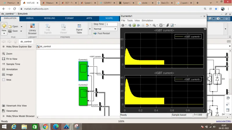
When Q1 and Q4 are triggered(shown in scope) , the Motor is in Forward Direction and the current appears for the first half of the cycle.
For second Half (after 0.5 secs), Q2 and Q3 are get triggered, and the Motor runs in a Reverse Motoring Quadrant.
In this Quadrant , both Speed and the Torque are negative .The Results are given below,
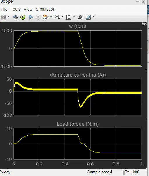
For 0 to 0.5 secs, the motor in Foward motoring. The Armature current ,Speed,Torque are in Positive condition.
After 0.5secs to 1 sec, the motor runs in reverse motoring. The armature current,Speed and Torque are in negative direction.
Now, the armature currents are getting higher at the time of Forward motoring triggering and reverse motoring triggering time.
Now this fluctuation is due to the Duty Cycle percentage.
Duty cycle means, the Ton Time to the Total Time.
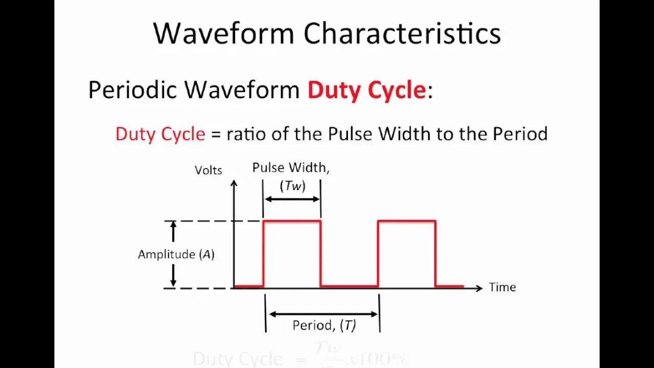
In order to reduce the terminal voltage to thge desired armature voltage, duty cycle is used.
When we tune the duty cycle to reduce the armature current fluctuation, the results are.
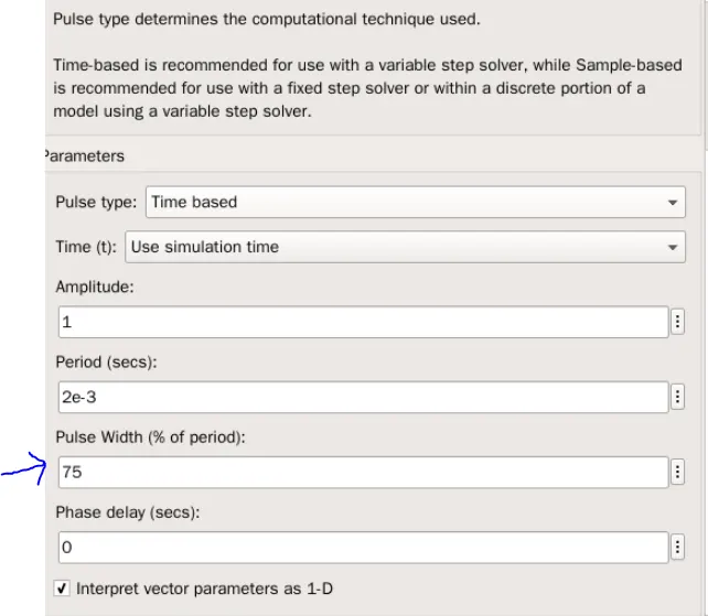
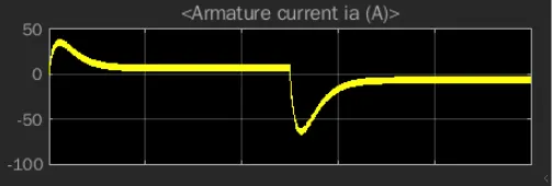
After Changing the Pulse Width percentage to 50% , the armature fluctuation got reduced,
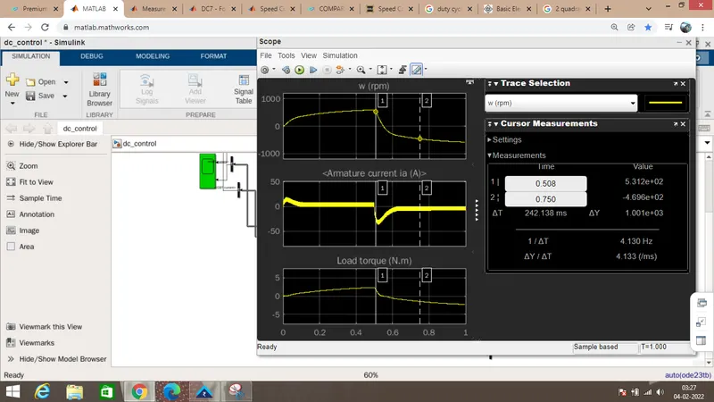
After change in the Pulse width variation, the armature current fluctuation reduced, and at the same time,Torque and speed also get reduced.
On Comparing H bridge with DC7 -4 Quadrant Bridge,
| Sl.No | H Bridge | DC-7 Four Quadrant Chopper |
| 1 | 2 Quadrant Operation | 4 Quadrant Operation |
| 2. |
Forward and Reverse motoring can be done |
Forward Motoring, Reverse Motoring, Forward Regenaartion, Reverse Regeneration. |
| 3. |
BJT is used in this Bridge |
IGBT is used in this Chopper |
| 4 |
Less Maintainace than IGBT bridge |
Highly effieint that H Bridge in Performance |
| 5 | Forward and Reverse Motoring operation can be done. | All the variation in the configuration can be mixed |
| 6 | Any two quadrant condition can be achieved. | Speed Positive, Torque Positive,&Speed Positive ,Torque Negative& Speed Negative, torque Negative,&Speed Negative ,Torque Positive |
| 7 | This BJT H bridgr in the model can only used for Forward and Reverse application of motor | Widely used for industrial application |
| 8 | Switching smoothness is not as much when compared to DC 7 Chopper | Switching smoothness to get accurate speeds of the motor |
| 9 | Any two of the switching BJTs are triggered at a time. | Each MOSFET is triggered with various condition for motoring and regenerative . |
Scope result of the DC 7 Chopper
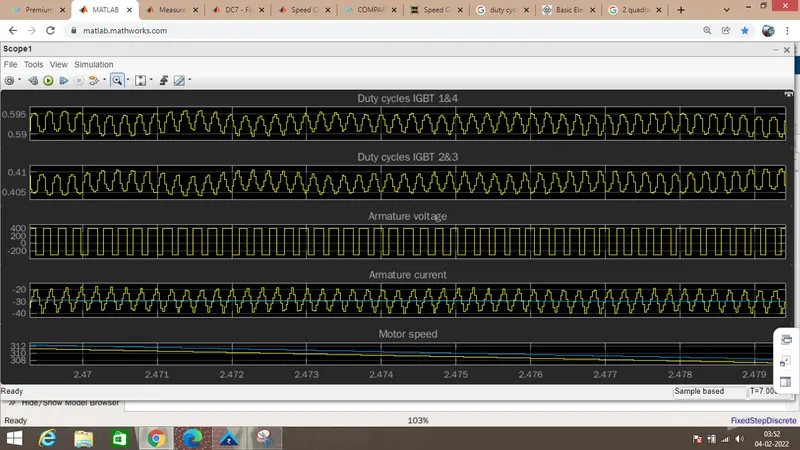
The pulse width is so smooth to smoothen the voltage and the armature current fluctuation has been removed in all quadrant operation.
2.Develop a 2-quadrant chopper using simulink & explain the working of the same with the relevant results.
Simulink Block:
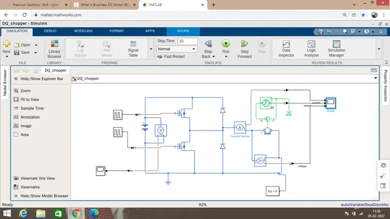
2 Quadrant Chopper consists of 2 MOSFET and 2 Diode
Mosfet acts a pulse actuated switch and Diode is used for Uni-Directional Power Flow.
when pulse Signal given to Mosfet 1, the current flows in a positive direction and the motor works in Forward Motoring.
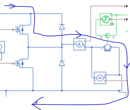
when Mosfet 2 closed and the Mosfet 1 opens, the Forward Reganarative mode will happens.
The Scopes are
Voltage Across the motor
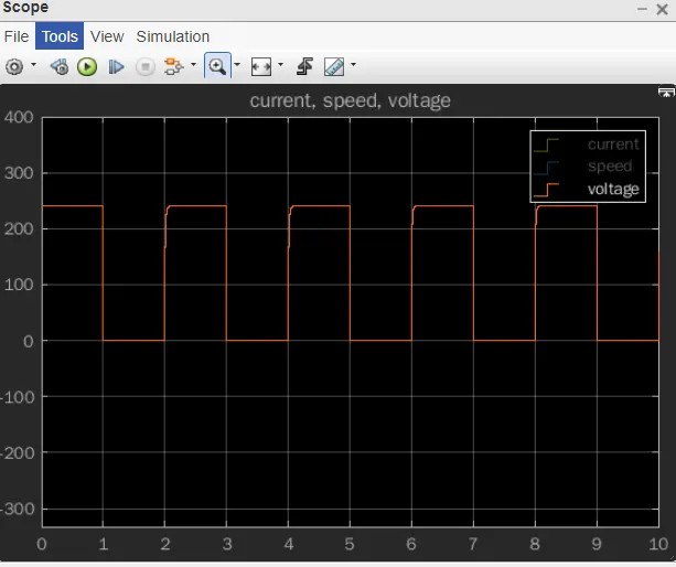
Voltage is pulsated for both oprerations.When Mosfet 1 is closed , the circuit got close and the voltage is Positive .When the Mosfet 1 open and Mosfet 2 Closed, Voltage becomes Zero.
Current Results
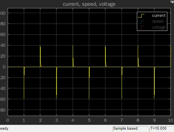
Current Flows in a Positive Direction in Forward Motoring and Negative Current at the Forward Regenative Torque
Speed
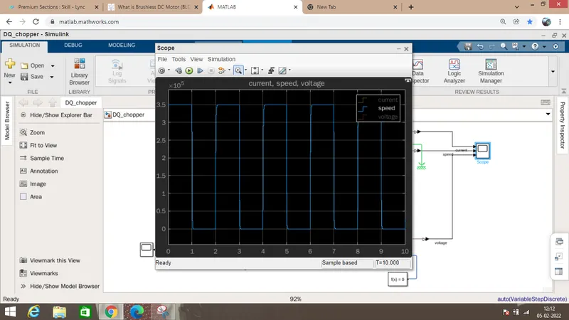
In @ Quadrant operation,
Speed will be Positive and the Torque is negative at the Forwar Regenrative condition.
Speed is not negative at the second Quadrant, it is in 0 level.
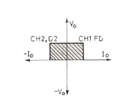
Voltage is Positive and the current will be negative.
Voltage at the Source
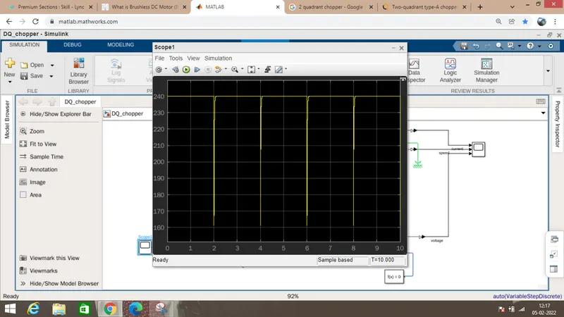
From Speed , Voltage across the Load (Vo), Current waveform, it satisfies the 2 Quadrant operation.
BLDC:
- Brushless Direct Current motor which is simply the DC motor without Brushes.
- Brushes are used for the commutation brushes.
- Commutation means, changing the phases of the stator coil winding, which is the basic principle of working of a DC motor.
- Brushes are mechanically used to commutate. Due to mechanical commutation, the high speed and performace are not achieved
- BLDC came into the technology to overcome the brushed DC motor.
- In BLDC ,Electronic commutation is prefered for the operation
Construction
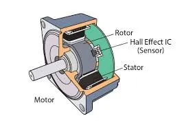
The essential compenents of BLDC motors are
- Permanent magnet Rotor
- Stator Winding
- Hall Effect Sensor
Stator:
1.Stator of a BLDC motor made up of stacked steel laminations to carry the windings.
2.These windings are placed in slots which are axially cut along the inner periphery of the stator.
3.These windings can be arranged in either star or delta. However, most BLDC motors have three phase star connected stator.
4.Each winding is constructed with numerous interconnected coils, where one or more coils are placed in each slot. In order to form an even number of poles, each of these windings is distributed over the stator periphery.
Permanent Magnet Rotor:
1.BLDC motor incorporates a permanent magnet in the rotor.
2.The number of poles in the rotor can vary from 2 to 8 pole pairs with alternate south and north poles depending on the application requirement.
3.In order to achieve maximum torque in the motor, the flux density of the material should be high. A proper magnetic material for the rotor is needed to produce required magnetic field density.
Hall sensors
1.Hall sensors are used to define the state or position of the rotor.
2.The hall sensor send the feed back to the control board to trigger the phases of the stator winding.
3.On taking the feedback from the Rotor position, the stator coils are energized accordingly for the rotation.
Working Principle:
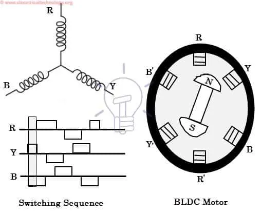
BLDC motor works on the principle of Lorentz Law .
According to the Law, when a current carring conductor placed inside the magnetic field, it experience the force.
In BLDC motor, the current carrying conductor is stationary while the permanent magnet moves.
When the stator coils are electrically switched by a supply source, it becomes electromagnet and starts producing the uniform field in the air gap. Though the source of supply is DC, switching makes to generate an AC voltage waveform with trapezoidal shape. Due to the force of interaction between electromagnet stator and permanent magnet rotor, the rotor continues to rotate.
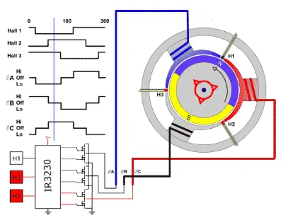
With the switching of windings as High and Low signals, corresponding winding energized as North and South poles. The permanent magnet rotor with North and South poles align with stator poles causing motor to rotate.
Motor produces torque because of the development of attraction forces (when North-South or South-North alignment) and repulsion forces (when North-North or South-South alignment). By this way motor moves in a clockwise direction.
Advantages of BLDC Motor
- It has no mechanical commutator and associated problems
- High efficiency due to the use of permanent magnet rotor
- High speed of operation even in loaded and unloaded conditions due to the absence of brushes that limits the speed
- Smaller motor geometry and lighter in weight than both brushed type DC and induction AC motors
- Long life as no inspection and maintenance is required for commutator system
- Higher dynamic response due to low inertia and carrying windings in the stator
- Less electromagnetic interference
- Quite operation (or low noise) due to absence of brushes
Disadvantages of Brushless Motor
- These motors are costly
- Electronic controller required control this motor is expensive
- Not much availability of many integrated electronic control solutions, especially for tiny BLDC motors
- Requires complex drive circuitry
Applications of Brushless DC Motors (BLDC)
Brushless DC Motors (BLDC) are used for a wide variety of application requirements such as varying loads, constant loads and positioning applications in the fields of industrial control, automotive, aviation, automation systems, health care equipments, etc. Some specific applications of BLDC motors are
- Computer hard drives and DVD/CD players
- Electric vehicles, hybrid vehicles, and electric bicycles
- Industrial robots, CNC machine tools, and simple belt driven systems
- Washing machines, compressors and dryers
- Fans, pumps and blowers.