Week-11 Challenge: Braking
- For a defined driving cycle, calculate the energy required for braking.
Breaking Energy
Braking energy is defined as the kinetic energy produced for the given period of time by the machine when driving electrical energy is cut off. It may be in Forward Direction or Backward Direction.
Two Braking Functions are:
1.Forward Braking
2.Reverse Braking
Braking Energy=0.5*m*V^2
m=mass of the vehicle
V=Velocity of the vehicle
Vi=Initial velocity
Vf=Final Velocity
Braking Energy=0.5*m*(Vi-Vf)^2
Initial Velocity=60kmph
final velocity=0kmph
Time=1 secs
Mass of the vehicle=1200Kg
Braking Energy =0.5*1200*60*60
=2160000joules
=2160kJ
=2160
=0.6kwh is used when decelaratig from 60kmph to 0kmph
In same way,
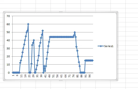
Total Braking energy for whole operation is 6242400
=6242.40KJ
=1.734KWh energy required for braking.
2.Why electric motor can’t develop braking torque at high speed similar to starting? How electric and mechanical brakes are coordinated?
Braking Torque occurs when the vehicle moves freely irrespective of the load .
Torque refers to the force , which tends to rotate the rotor of motor and connected Load.
When Motor torque overcomes the Load Torque, then only the motor can start rotating on its axis.
So While Forward Traction,The Torque required is higher.
Which is given as the Formula
Tm=Tl+Inertia
This is the formula for the torque of the motor, includes inertia .
While Decelaration,
Tm=Tl-Inertia
That means the load torque only applied while the motor in decelaration.
If the Torque acquired during acceleration is 100NM,The same -100 NM will not be acquired during the Decelaration.
The Kinetic energy is the only source of energy for rotation while decelarating ,so the torque created during decelaration is less.
The driver’s braking force commands are related to driving safety. The value of braking force
represents the braking distance and time the driver requires to stop the vehicle.
If the driver’s braking force command is large, it means the vehicle should be stopped in a short distance and time.
At that time, we should decrease the proportion of regenerative braking force; when the driver’s braking force command is medium, the ratio of the regenerative braking force used should be increased; and in the last condition, the driver’s braking force command is small, so we can apply a large regenerative braking force to the vehicle
There are two ways to coordinate the regenerative torque of the motor and the friction torque of the hydraulic unit: parallel and series.
In parallel braking, the regenerative torque of the motor is exerted on the driving axle directly in addition to the friction torque, while series braking allows independent modulation of the hydraulic brake torque of each axle according to the regenerative torque, and thus potentially more kinetic energy can be recovered than with parallel braking.
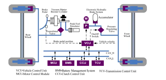
The LF620 EV layout determines that regenerative braking torque can only operate on the front
wheels.
The electronic hydraulic brake system consists of a motor, a pump, an accumulator and a
pressure regulating valve.
When braking, the VCU calculates the target deceleration and target brake force according to the brake pedal stroke, and the distribution between front and rear wheels.
The brake pedal force is transmitted to a master cylinder through a vacuum booster. The master cylinder pressure is supplied to the rear wheels cylinder through a proportional valve.
The VCU also calculates the distribution between regenerative brake force and friction brake force according to vehicle velocity,SOC and other information.
Then an on-off switch controls the motor work or not to keep the accumulator pressure in a proper range.
The regenerative brake force and the friction brake force work together, and the target deceleration is obtained.
Due to the fact the front wheel pressure is supplied by the electronic hydraulic brake system, the driver would notice an unfamiliar brake pedal feeling compared with a conventional brake system.
Therefore, a pedal feel simulator is added to consume the brake oil flowing from the master cylinder and simulate the front wheels cylinder characteristics to maintain a similar brake pedal feeling.
When batteries’ SOC is lower than 10%, the inner resistance of the batteries has a high value and is unsuitable for charging, so at this time, the proportion of the regenerative braking force should be low.
when the value of SOC is from 10% to 90%, the batteries can be charged with a large current and the proportion of the regenerative braking force should be increased correspondingly.
when SOC is bigger than 90%, the charging current should be decreased to prevent deposit of li-ion and the value of regenerative braking force should be low, too.
Conclusion:
The Braking logics reads the regenarative braking and apply the mechanical braking level with respect to the braking energy available while decelarating.
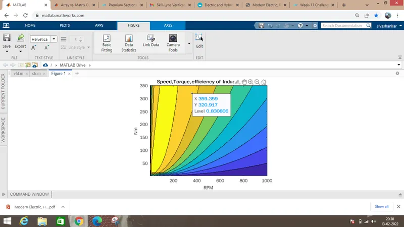
3.Make a MATLAB program which plots contour of given motor speed, torque and efficiency values. Attach the code as a .m file attach a screenshot of all the plots.
Matlabcode
Scope
Losses in motor are;
1.Copper Loss=Kc.T2
2.Iron Loss=Ki.w
3.Windage loss=Ki.w^3
4.Constant=c
Total loss is given as
=Kc*T2+Kiw+Kww^3
Output Power=w*T;speed *Torque
Pin=Pout+Total loss
Efficiency=Pout/Pin
All speed , torque and efficiency is plotted in contour.