Week-6 Challenge: EV Drivetrain
Which types of power converter circuits are employed in electric and hybrid electric vehicle?
Power Converter are of following Types
1.AC- DC CONVERTER-RECTIFIER
2.DC-AC CONVERTER-INVERTER
3.DC-DC CONVERTER-CHOPPER
4.AC-AC CONVERTER-CYCLOCONVERTERS
In Electrical vehicles, the first 3 types of Power Converters are used.
1.Rectifier
2.Inverter
3.Chopper
What are the purpose of Power Converters?
Purpose of Power Converters is to convert certain characteristics of Electrical Power in to another.
For ex., AC-DC,DC-AC,DC-DC.
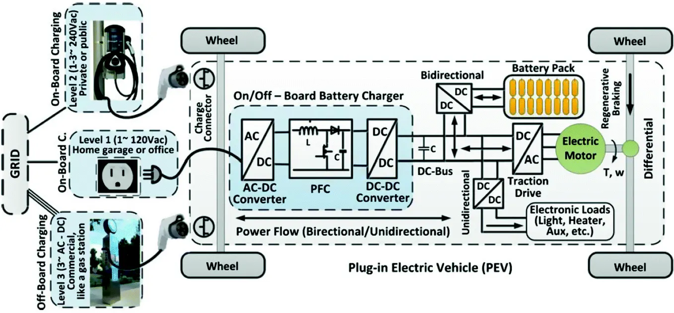
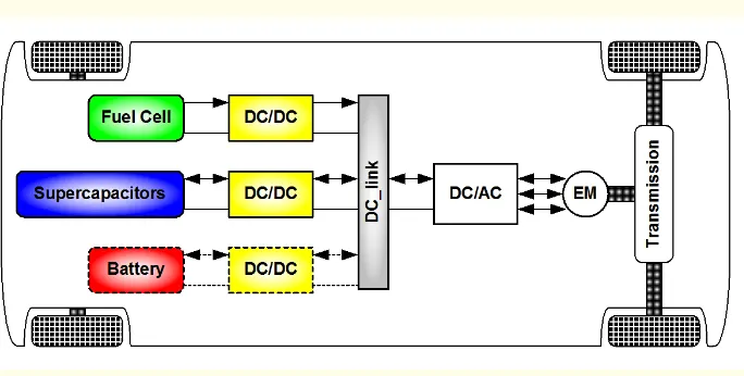
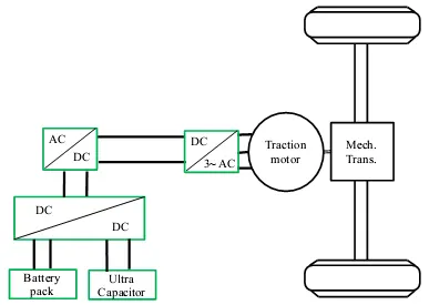
In this diagram, the usage of Power converters are given.
In Short,
AC-DC Rectifier is used for Charging purpose of the vehicle. In this, the 230V AC is converted to DC voltage of desired voltage using step up or step down transformer at the source.
DC-DC Chopper is used to Convert DC of high voltage to DC of Low voltage, as it is need of accessories supply,and to charge the battery with the limiting voltage.It is Bi-Directional, as the voltage flows from Battery to Motor and From motor to Battery.
DC-AC Inverter- Battery supply is DC and in order to supply voltage from the Battery, the voltage are to be converted from DC to AC voltages. It is also Bi-Directional.
Lets see How these conveters works...
Rectifier
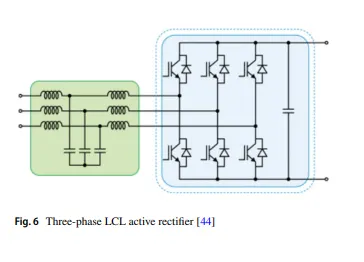
1.One of the most widely used bidirectional AC/DC converter is the three-phase LCL active rectifer.
2The advantages of this type of converter are low harmonic input currents, bidirectional power fow and power factor (PF) regulation.
3.This converter has been used to increase the power density and to achieve low current harmonics distortion.
4Another advantage is that it allows the creation of a bipolar dc bus which can be used for the implementation of partial-power converters.
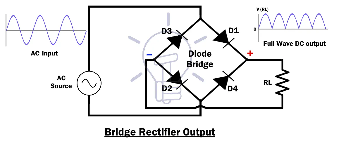
There are different types of rectifiers classified based on their output.
1.Single Phase Rectifier
2.Three Phase Rectifiers
3.Controlled Rectifiers
4.Uncontrolled Rectifiers
5.Half Wave Rectifiers
6.Full Wave Rectifiers
7.Bridge Rectifiers
8.Center-Tapped Rectifiers
Working Principle of Bridge Rectifier
The source can be from a transformer that is used to step up or down the voltage or it can be from the mains of our domestic power supply. we are using a 6-0-6 centre tapped transformer for providing AC voltage.
In the first phase of working of the rectifier, during the positive half cycle
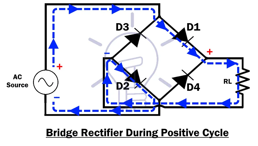
Diodes D3-D2 get forward biased and conducts. Diodes D1-D4 gets reversed biased and do not conduct in this half cycle, acting as open switches. Thus, we get a positive half cycle at the output.
In the negative half cycle, diodes D1-D4 get forward biased, and start conducting whereas diodes D3-D2 gets reversed biased and do not conduct in this half cycle.
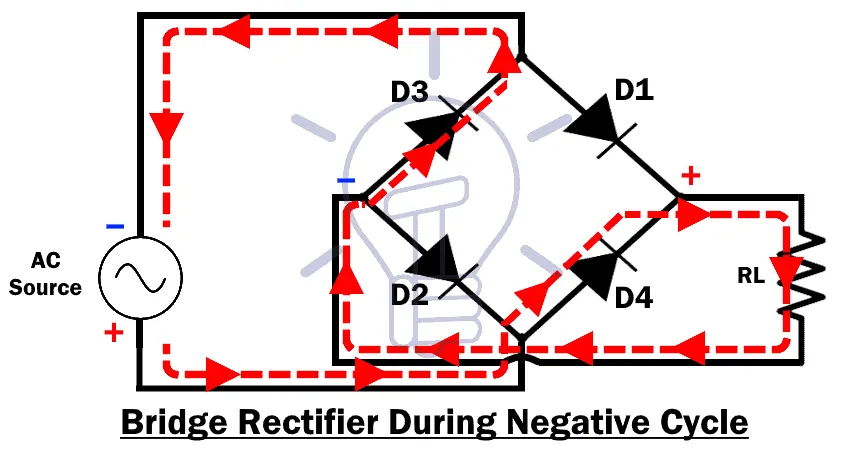
Again, we get a positive half cycle at the output. At the end of the rectification process, the negative part of the AC current is converted into a positive cycle.
The output from the rectifier is two half-positive pulses with the same frequency and magnitude as that of the input.
In contrast to the working of a half-wave rectifier, the full bridge rectifier has another branch which allows it to conduct for the negative half of the voltage waveform which the half-bridge rectifier had no means of doing.
So the average voltage at the output of the full bridge rectifier is double than that of the half-bridge rectifier.
Although we use four individual power diodes to make a full wave bridge rectifier, pre-made bridge rectifier components are available “off-the-shelf” in a range of different voltage and current sizes that can be used directly to make a working circuit.
The output voltage waveform after the rectification is not a proper DC, so we can try to make it more into a DC waveform using a capacitor for filtering purpose.
Smoothing or reservoir capacitors that are connected in parallel with the load across the output of the full wave bridge rectifier circuit increases the average DC output level to the required average DC voltage at the output because the capacitor not only acts as a filtering component, but also periodically charges and discharges effectively increasing the output voltage.
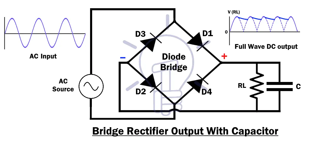
Capacitor charge till the waveform goes to its peak and discharges uniformly into the load circuit when waveform starts going low. So when the output is going low, capacitor maintains the proper voltage supply into the load circuit, hence creating the DC.
DC-DC Converter-CHOPPER
Chopper plays a significant role in Electrical vehicle.Chopper has to work in a bidirectional way, as the power flows To and fro motion.
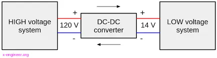
In chopper , DC is Converted into DC from High voltage to Low Voltage.
High Voltage of DC from the Battery is converter to Low voltage DC for the supply of Controllers, Acessories working with 12 or 24vDC.
Chopper is so sensitive to the voltage and limit the volatge to the specified Limit.So that the Over voltage will not affect the system using of voltage regulator ICs.
a DC to DC converter is a category of power converters and it is an electric circuit which converts a source of direct current (DC) from one voltage level to another, by storing the input energy temporarily and then releasing that energy to the output at a different voltage. The storage may be in either magnetic field storage components (inductors, transformers) or electric field storage components (capacitors).
. A bi-directional converter can move power in either direction, which is useful in applications requiring regenerative braking.
DC-AC Converter(Inverter)
IN electric Vehicle, Inverters are used to Convert DC to AC for energizing Motor used for transmisiion.
Circuit Diagram for Inverter
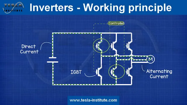
Working principle
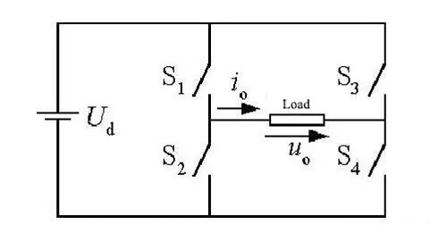
Four switches from S1 to S4 constitute two bridge arms, of which S1 and S2 shares the same bridge arm, and S3 and S4 shares the other same bridge arm. When S1 and S4 are connected, and S2 and S3 are disconnected, Uo = Ud can be obtained on their load resistance. On the contrary, when S2 and S3 are connected, and S1 and S4 are disconnected, Uo = -Ud can be obtained on the load resistance. By continuous operation with switch like this, the AC waveform can be obtained on the load, which completes the process of converting DC into AC.
Waveform
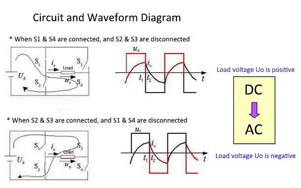
It should be noted that the switch on the same bridge arm cannot be connected simultaneously, so as to avoid short circuit of power supply, and that the frequency of AC can be changed by changing the switch frequency. In fact, the four switches in the figure above are ideal models for various semiconductor switching devices, and common semiconductor switching devices in inverters include thyristors, field effect transistors and insulated gate bipolar transistor (IGBT). For example, the following figure is a switching circuit consisting of a field effect transistor.
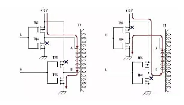
The switching device of the circuit is composed of N-channel field transistor and P-channel enhancement field effect transistor, which forms push-pull output. When the driving signal is low-level L, it is the P-channel field effect transistor, and when the input signal is high-level H, it is N-channel field transistor. This alternating conduction can avoid the risk of short circuit caused by the simultaneous conduction of two switches from the same bridge arm. The working process is as follows: the field effect transistors of TR3 and TR4 are from the same bridge arm, TR5 and TR6 are from the other same bridge arm. The conduction of four switches controlled by pulse signals closes to produce alternating signals, which are applied to the low-voltage winding of the transformer, and the high-voltage winding of the transformer will be induced high-voltage AC, so as to complete the inversion from DC to AC.
Conclusion
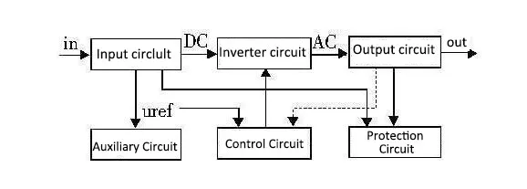
The above is only the basic working principle of inverters. In practice, the application of inverters is absolutely much more complex. An inverter is completely composed of the main circuit, control circuit, drive circuit and auxiliary power supply.
- Main circuit
The main circuit includes various switching circuits to complete the inversion, which are mainly composed of DC power supply (capacitor), buffer, switching bridge circuit, filter and transformer, so as to complete the energy-level processing. - Drive circuit
Drive and ensure the reliable switching on/off of the field effect transistors and other switching devices according to the switching signal of the control board. - Control circuit
Collect feedback from main circuit, realize control algorithm and protection strategy and obtain switch signal. - Auxiliary circuit
Auxiliary power supply and circuit of control chip and driver chip.
2.An Electric Vehicle's powertrain with 72V battery pack in shown in the diagram below. The duty ratio for acceleration operation is 'd1' and for the braking operation the duty ratio is 'd2'.
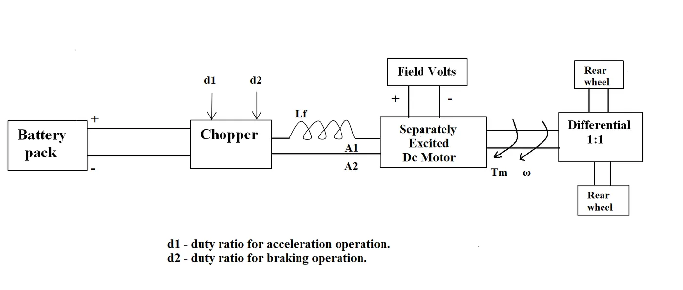
The other parameters of the electric vehicle is given below,
Motor and Controller Parameters:
Rated Armature voltage= 72 V
Rated armature current= 400 A
Ra= 0.5Ω, KΦ= 0.7 Volt second
Chopper Switching frequency= 400 Hz
The vehicle speed-torque characteristics are given by the below equation

What is EV steady state speed if duty cycle is 70%?
The speed given as
w(omega)=((Vt/KΦ)-(Ra/(KΦ)^2))T
Votage=72V
With the Duty cycle of 70%,Voltage output=72*(70/100)=50.4V
w(omega)=((50.4/0.7)-(0.5/(0.7)2))T
=72-1.02T
T=(72-w)/1.02=70.58-0.98w
T=70.58-0.98w
The given equation is,
On equatin both equations,
70.58-0.98w=24.7+(0.0051)w^2
0.0051w^2+0.98w-45.88=0
This is the quadratic equation as ax2+bx+c=0
a=0.0051,b=0.98,c=-45.88
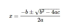
w=(-0.98+Sq.rt of((0.98)^2-(4*0.0051*(-45.88)))/(2*0.0051)
w=38.92,-231.08
As we neglect the negative,
w=38.92rad/s
w=(38.92*60)/2*pi=371.65rpm
3.Develop a mathematical model of a DC Motor for the below equation using Simulink.

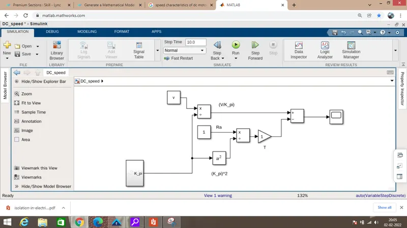
Voltage is created in the workspace with the rising values.
K-phi is calculated using the formula
K-phi=Eb/w(omega)
Eb=Back emf
The W(omega) values are plotted.
Scope of the speed for different voltage and K_pi inputs.
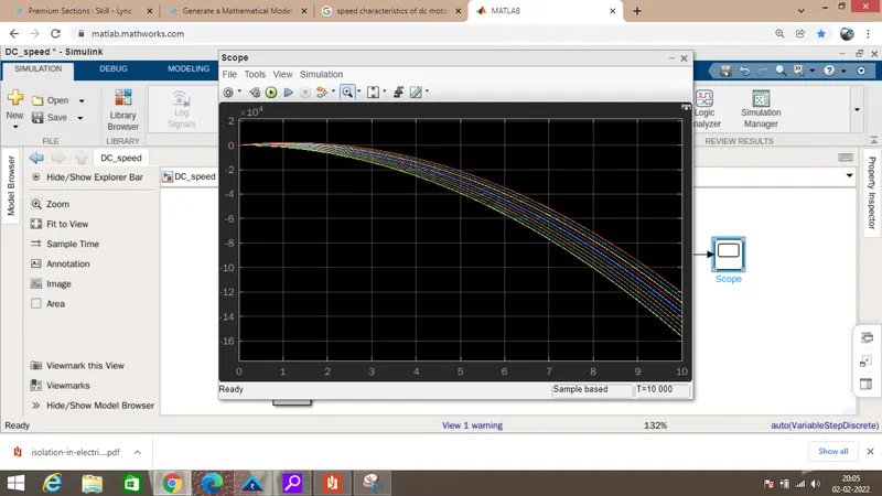
This is the mathematical model using Simulink.
At initial level, Torque is higher. when the speed getting rise, the torque is gets low.
At no load condition, Torque becomes zero and the speed becomes higher.
Eb is the back emf which created by the motor. Back emf is higher during the degenrative braking.
The power flows from the motor to Battery for charging the vehicle.
4.Refer to the blog on below topic:
Induction Versus DC brushless motors by Wally Rippel, Tesla
Explain in brief about author’s perspective.
According to Author perspective, he didnot dominate with one another. He explained the advantages and limitations of the BLDC and Induction motor.
Both motors have their own characteristics, advantages and disadvantages.Author explains each significant changes of BLDC with induction motor.Let us have a look...
Structure:
Stator have 3 phase distributed winding structure ,where as BLDC also have the same set up.But, in rotor, stacked steel laminations with buried periperal conductor structures are used in Induction motor,and 2 or 3 Permanent Magnets are used for rotor structure.
Starting Torque:
BLDC motor needs an inverter to produce the starting torque, where as Induction motor does not need such arrangement for starting . It will produce starting Torque itself with the power supply.
Torque efficieny:
Though, the induction motor producec torque by itself,it has limiting starting torque and limited peak torque comapred to BLDC.BLDC has high torque performance.
Even Induction motors are connected with inverter also, the torque performance is lesser than BLDC.
Control Inverter
BLDC needs absolute position sensor for controlling the speed of the rotor whereas induction motor need speed sensor for control.
Without Controller ,BLDC motors are useless.Without converters ,Induction motors will run.
Induction motors are not easy to control where as DC motors are controllable.
Efficiency(Power Factor)
BLDC is having hagher efficiency when compared to Induction motor in accordance with the Power Factor.BLDC inverter has unity Power Factor and induction motor has 0.85 Power Factor.
Loss:
In BLDC Motor, the magnetic fields are adjusted, so, at the low speed ranges, the towrque will be low, B is low.I^2R Loss is low. Accordingly, in induction motor, Magnetic and conduction losses are low.
Because, B field is adjustable in Induction motor, but in BLDC, it is not a easy way.
Slip
In BLDC motor, no slip speed occurs. But in Induction motor, there is a slip.
Cost:
BLDC motors are costly when compared to Induction motors. Permanent magnets are costly when compared to copper windings in Induction motor. Induction motor needs lesser inverter drive rating , so, the costs are low.
Though, costs are low, the performance of BLDC is quite high when compared to Induction motors.
Conclusion:
Though both the motors have their significant advantages and disadvantages also. Both have their specific positive things where as another lag. In this EV race, both motors have tremendous role and have better future with respect to their improvements.