Week-7 Challenge: DC Motor Control
1.Speed control of a DC motor using BJT H-bridge :
BJT H-bridge :
There are two terminals ‘A’ and ‘B’ of DC motor.
Now if we connect terminal A with +Ve supply and terminal B with –Ve supply or ground the current will flow from motor from A to B and motor will rotate in one direction – say clockwise (CW) or forward direction.
Now as shown in second figure we change the supply terminals. Now B is connected with +Ve and A is connected to ground. The current will flow from motor from B to A and motor will rotate in other direction (counter clockwise – CCW or reverse).
Four switches are connected in between +Ve supply and ground and DC motor is connected in between two switches as shown.
Such circuit arrangement is known as H-bridge because it looks like letter ‘H’ (H-bridge circuits are most widely used in DC motor drivers). Let us see how it gives reverse supply to motor.
Operation of H-bridge :
If SW1 and SW4 are pressed simultaneously then current will flow from +Ve – SW1 – A – B – SW4 – Gnd. So motor will rotate in one direction. Open (release) SW1 and SW4 to stop motor. Now if SW2 and SW3 are pressed current will flow from +Ve – SW2 – B – A – SW3 – Gnd. So motor gets reverse supply and it will rotate in another direction.
We all know that transistor works as switch. For NPN transistor if we give +Ve input to base it will turn ON and if we give 0 input it will be turned OFF.
So in this circuit if Q1 and Q4 are turned ON simultaneously the motor will rotate forward and if Q2 and Q3 are turned ON then motor will rotate reverse.
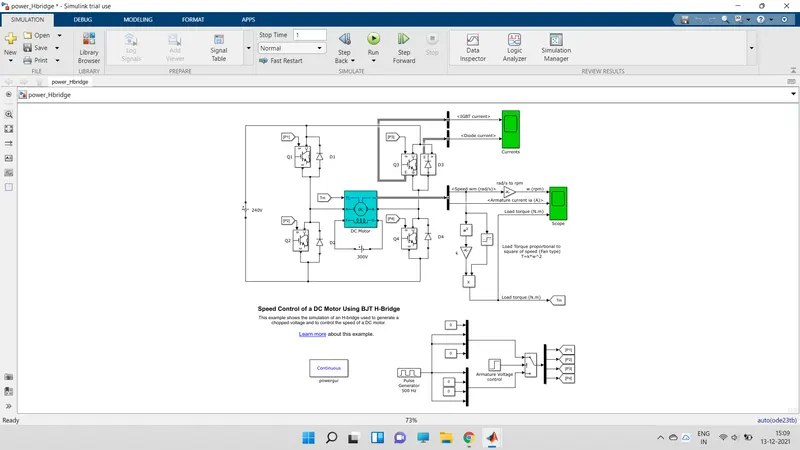
Default simulink model for speed controll of dc motor using H bridge :
The model mainly consists of H bridge made with four IGBT switches , dc machine ,scopes for diifrent plots,switch ,gain and pulse generator blocks
Machine parameters :
The mchine used in this model has the ratings of
o/p power =5hp
voltage =240 v;
speed=1750Rpm;
field supply =300v
power semiconductor switch parameters :
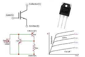
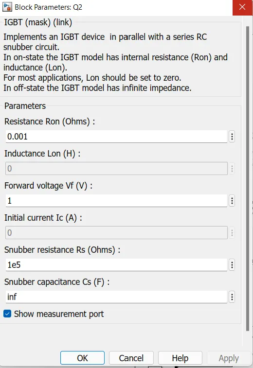
The switch used in this bridge is a IGBT switch.
The following are the input parameters of the switch .
pulse generator input parameters :
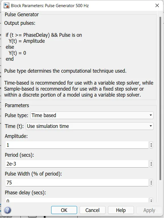
The pulse generator the puse to gates of the supply,at respective times.
For this model the duty cycle is 70 % so the pulse width is given as 75 and the time period is 1/f.
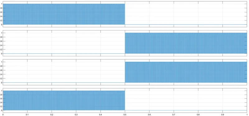
Pulse generator generated plots wrt time to the H-bridge :
During 0 to 0.5 the swithches 1&4 are on state .
From 0.5to 1 the switches 2&3 are on.
step block parameters :
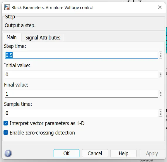
This is given as reference to the switch to check the criteira in the switch.
0to0.5 the second bus is activated .
from 0.5 to 1 first bus is activated .
Motor characteristics plot :
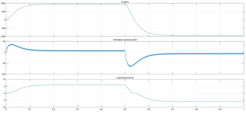
From 0 to 0.5 the current in the armature is from A to AA so the motor rotates in positive direction.ie, speed is postive near 1000RPM.
From 0.5 to 1 the current in the armature is changes direction from AA to A so the motor rotates in reverse direction.ie, speed is negative near -1000RPM.
The same way torque also negative value if rotation direction changes.
IGBT and diode current plot :
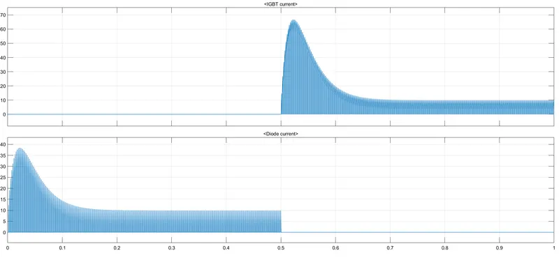
The IGBT switch conduct's in the 0.5 to 1 ;during 0 to 0.5 the stored current freewheels in the diode next to it.
b.armature current shootup :
As we know that the dc macine armature current is given by ,
Ia=net voltage /Ra
Ia=V-Eb/Ra..... ( eq-1)
where ,
V is supply voltage
Eb is the back emf
Ra is the armature resistance .
we know that the speed N is directly proportional to back emf N∝Eb
case 1:when the speed 0 or less ie, starting condition
the Eb is less due N is low
This means the from the eq 1 we can say that the current will be more (Ia).
case 2:when the speed is constant(under no load condtion), then back emf will be more
if the back emf is more the the armature will draw less current.
case 3:when the speed is decresing(under load condtion), then back emf will decrese
Speed is decresing means back emf is decreses so the motor consumes more current.
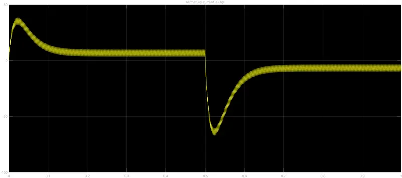
That's why when the motor is starting the speed is low almost zero so ,the back emf is less so the motor will draw huge amount of current at the time starting.
The below plot shows the armature current of a dc motor .we can clearly observe the peak shootout at the time of starting in one direction and peak shootout in reverse direction current also
c.The Four-Quadrant Chopper DC Drive (DC7) block :
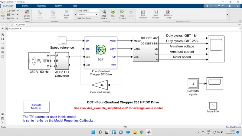
The below model represens the Four-Quadrant Chopper DC Drive (DC7) .
The block mainly consists of Four-Quadrant Chopper DC Drive, ac to dc converter, 3 phase supply,controll blockand a scope.
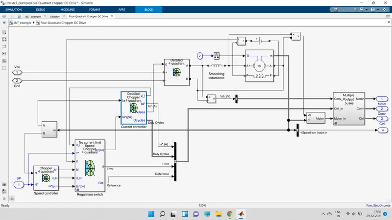
Four-Quadrant Chopper DC Drive :
This block mainly consists of dc machine block ,current controller,4 quadrant drive,regulation switch, and some subsystem blocks.
We can vary the each and every value of the component indidvidualy from open the block.
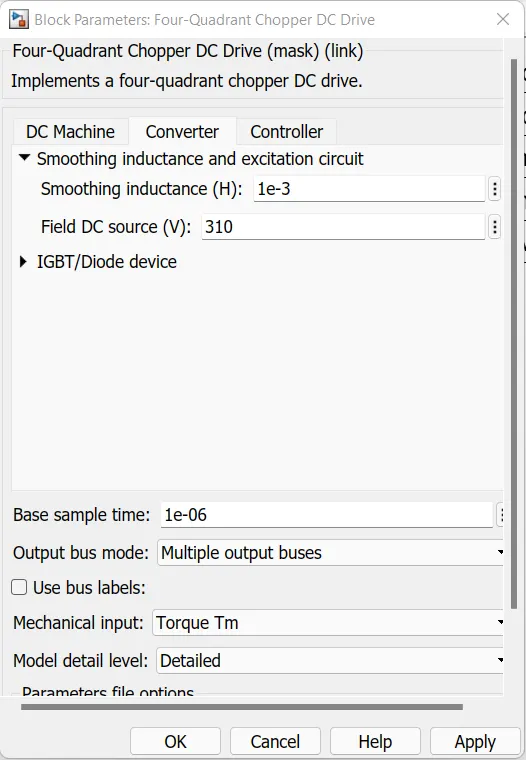
This is the block for varying the diffrent parameters of the drive :
We can simply change the different parameters of the diffrent components of drive without going inside the mask.
The motor and contoller , converter parameters we can change from here.
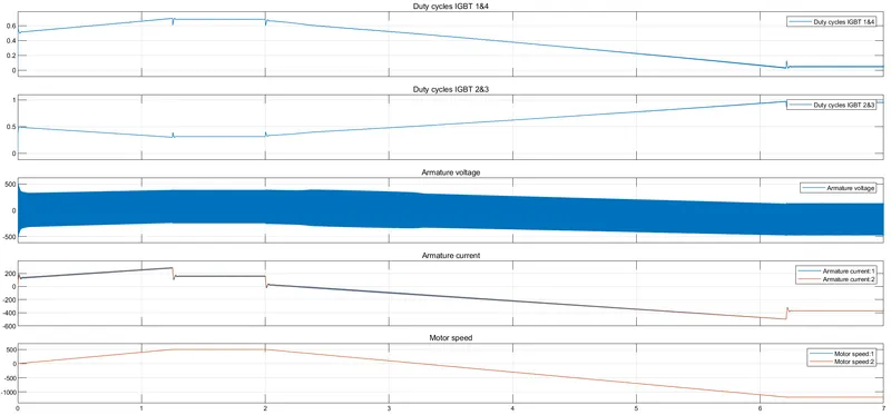
The plot of the model for default conditions :
The pot gives us the duty cycles of the igbt switches and armature voltage and currents,speed of the drive motor.
The parameters are going to change if we wish to change the output characteristics .
Comparision of the Four-Quadrant Chopper DC Drive (DC7) block and Speed control of a DC motor using BJT H-bridge :
The Speed control of a DC motor using BJT H-bridge model is for forword and reversing the motor directions.
The Four-Quadrant Chopper DC Drive (DC7) model gives the 4 modes of operation of the drive.ie, forword motoring and braking , reverse motoring and braking.
The Four-Quadrant Chopper DC Drive (DC7) model is complex model so it takes more time to run the simulation.
The Speed control of a DC motor using BJT H-bridge takes less time to run the simulation .
The Speed control of a DC motor using BJT H-bridge is defaultly set for 1sec run time for 1 cycle.
The Four-Quadrant Chopper DC Drive (DC7) is is defaultly set for 7sec run time for 1 cycle of operation.
The machine is used in H bridge model is to be changed for changing the parameters,but in case of four quadrant model we can chage the individual parameters.
The supply used in the H-bridge model is dc supply .
But incase of the four quadrant model the supply is 3 phase and it again converted into dc supply then it is fed to dc drive.
And the four quadrant model consits of many blocks like selector.for sellecting differnt arameters at the outside.
In case of h- bridge simple igbts used for switching .but incase 4 quadrant model it uses closed loop for controlling.
2.two quadrant chopper :
The Two-Quadrant Chopper block represents a two-quadrant controlled chopper for converting a fixed DC input to a variable DC output.
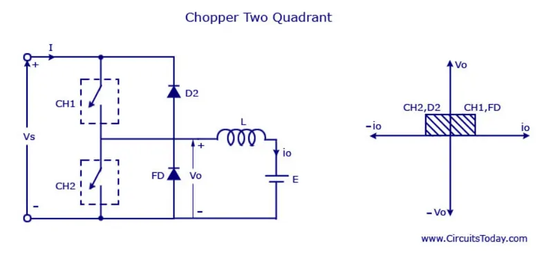
The average voltage will be always positive but the average load current might be positive or negative. The power flow may be life the first quadrant operation ie from source to load or from load to source like the second quadrant operation. The two choppers should not be turned on simultaneously as the combined action my cause a short circuit in supply lines. For regenerative braking and motoring these type of chopper configuration is used.
A 2-quadrant chopper model using simulink :
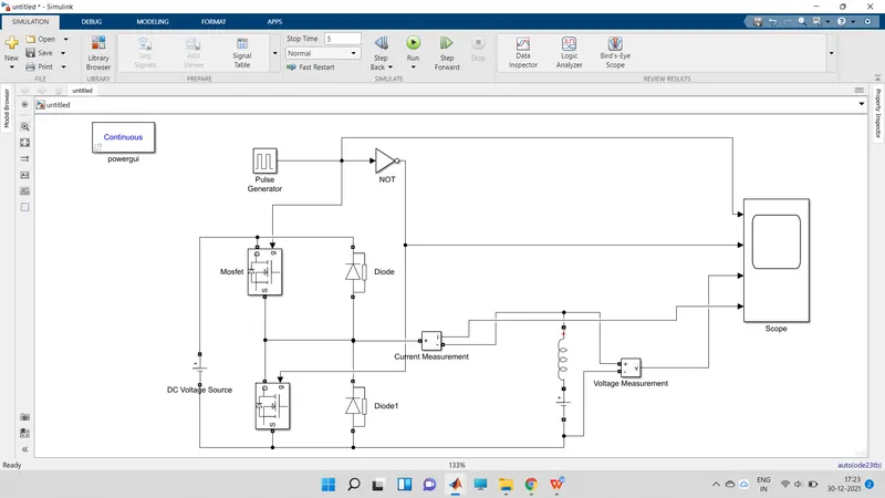
The below model shows the 2 quadrant chopper in simulink . this circuit is typically mosfets ,diodes ,voltage and current measurement and pulse generator ,voltage source,scope.
Sometimes a chopper may be required to provide a two quadrant operation by retaining the current direction in both motoring and braking modes. Such a Two Quadrant Chopper and its waveforms . The chopper permits a change in the polarity of terminal voltage keeping the direction of current constant. In S1 and S2 are the choppers working as electronic switches and D1 and D2 are the feedback diodes. Assuming continuous conduction, both S1 and S2 operate simultaneously.
When they are ON, the load current Id increases, with the rate of rise depending upon the back emf and torque of the machine. When they are OFF, the load current is fed to the supply through the diodes D1 and D2. The current decreases in this stage. it is clear that the load voltage is effectively negative when the diodes conduct. The average value of the output voltage of the chopper
The output plot for the 2quadrant chopper :
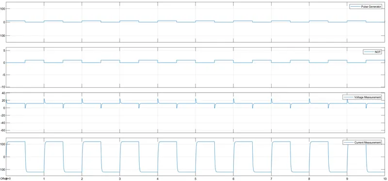
In this plot the ip pulses and voltage across load and load current is given.
The not gate is used to trigger the switches respectively.
The volatge is postive entirely but osillating in nature.
but the current direction changes from positive to negativeie, its direction in load changes periodically.
3.BLDC motor:
A brushless DC electric motor (BLDC motor or BL motor), also known as an electronically commutated motor (ECM or EC motor) or synchronous DC motor, is a synchronous motor using a direct current.(DC) electric power supply. It uses an electronic closed loop controll to switch DC currents to the motor windings producing magnetic fields which effectively rotate in space and which the permanent magnet rotor follows. The controller adjusts the phase and amplitude of the DC current pulses to control the speed and torque of the motor. This control system is an alternative to the mechanical commutator (brushes) used in many conventional electric motors.
These types of motors are highly efficient in producing a large amount of torque over a vast speed range. In brushless motors, permanent magnets rotate around a fixed armature and overcome the problem of connecting current to the armature. Commutation with electronics has a large scope of capabilities and flexibility. They are known for smooth operation and holding torque when stationary.
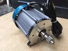
construction of BLDC motor :
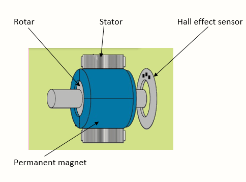
In this motor, the permanent magnets attach to the rotor. The current-carrying conductors or armature windings are located on the stator. They use electrical commutation to convert electrical energy into mechanical energy.
The main design difference between a brushed and brushless motors is the replacement of mechanical commutator with an electric switch circuit. A BLDC Motor is a type of synchronous motor in the sense that the magnetic field generated by the stator and the rotor revolve at the same frequency.
Brushless motor does not have any current carrying commutators . The field inside a brushless motor is switched through an amplifier which is triggered by the commutating device like an optical encoder.
The layout of a DC brushless motor can vary depending on whether it is in “Out runner” style or “Inrunner” style.
Types of BLDC motors:
Basically, BLDC are of two types, one is outer rotor motor and other is inner rotor motor. The basic difference between the two is only in designing, their working principles are same.
Inner rotor design :
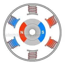
In an inner rotor design, the rotor is located in the centre of the motor and the stator winding surround the rotor. As the rotor is located in the core, rotor magnets do not insulate heat inside and heat get dissipated easily. Due to this reason, inner rotor designed motor produces a large amount of torque and validly used.
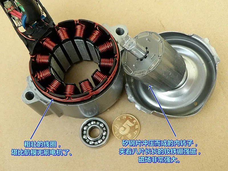
Outer rotor design :
In outer rotor design, the rotor surrounds the winding which is located in the core of the motor. The magnets in the rotor trap the heat of the motor inside and do not allow to dissipate from the motor. Such type of designed motor operates at lower rated current and has low cogging torque.
Advantages of bldc motor :
- Better speed versus torque characteristics
- High dynamic response
- High efficiency
- Long operating life due to a lack of electrical and friction losses
- Noiseless operation
- Higher speed ranges
- no sparks due to elimination of commutator
- less rotor inertia
Disadvantages of bldc motor :
- BLDC motor cost more than a brushed DC motor.
- The limited high power could be supplied to BLDC motor, otherwise, too much heat weakens the magnets and the insulation of winding may get damaged.
Working of bldc motor :
BLDC motor consists of the permanent magnet rotor and wound stator. The brushes motors are controlled using a three phase inverter. The motor requires a rotor position sensor for starting and for providing
commutation sequence to turn on the power device in the inverter that can be achieved by hall sensor.
Based on the rotor position, the power devices are commuted sequentially.
Stator windings of a BLDC motor are connected to a control circuit (an integrated switching circuit). The control circuit energizes proper winding at proper time, in a pattern which rotates around the stator.
The rotor magnet tries to align with the energized electromagnet of the stator, and as soon as it aligns, the next electromagnet is energized. Thus the rotor keeps running.
Commutator helps in achieving unidirectional torque in a typical dc motor.
Obviously, commutator and brush arrangement is eliminated in a brushless dc motor. And an integrated inverter/switching circuit is used to achieve unidirectional torque.
That is why these motors are, sometimes, also referred as ‘electronically commutated motors’.
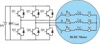
3-phase inverter circuit for BLDC motor :
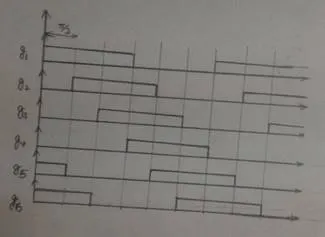
Working of a number of electric machines is closely tied to the frequency of the supply. Speed of electric motors is controlled by varying the frequency of supply. Frequency of the sinusoid obtained using the proposed method can be easily varied by controlling the period of pulses used to control the gates of MOSFETs. Hence they can have an effective application in electric drives. The output obtained is capable of driving a BLDC motor. The angular velocity can be controlled by varying the rate of switching of the gates.
The gates are controlled on the bases of required speed and controll .
The below plot is one of the controll of the BLDC motor.
SPEED TORQUE CHARACTERISTICS :
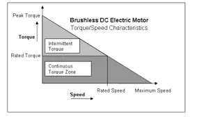
Applications that have frequent starts and stops and frequent reversals of rotation with load the motor, demand more torque than the rated torque. This requirement comes for a brief period, especially when
the motor starts from a standstill and during acceleration.
The motor can deliver a higher torque, maximum up to peak torque, as long as it follows the speed torque curve.
applications of BLDC motors :
- Brushless DC motors are used in hybrid vehicles, electric vehicles, and other electrical equipment.
- These motors are used in robotics for robotic arms.
- BLDC motors are used in computer hard drives and DVD players.
- These motors are used in fans, washing machines, dryers, pumps, blowers, and compressors.
- Used in drones
- domestic cealing fans.