Week-6 Challenge: EV Drivetrain
1.POWER CONVERTER :
A power converter can convert alternating current (AC) into direct current (DC) and vice versa; change the voltage or frequency of the current or do some combination of these.
It is a device with power semiconductor switches arranged in fashion to contoll or modify the input based on our requrement.
If it converts ac to dc ie, rectifier or controller circuit.
The inverter is device which converts dc to ac .
The power converter changes the form ie, AC to DC ,and DC to AC ,
And level of the wave of the supply.
The below is the block diagram represenntation:
power convertors in hybrid electric vehicle :
In HEV the battery is charged by the vehicle engine it self, the generator in car generates the ac supply so it is to be coverted into dc to charge the battery. so it requires a convertor circuit.
If the the motor used is ac motor for tractive effort , then an inverter circuit is required to convert battrey dc into ac supply for the motor.
converter or rectifier :
It converts ac supply to dc supply.
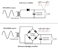
The following images represents the diffrent types of rectifiers
basically these are 3 types :
1.half wave rectifier
2.full wave
3.bridge rectifier
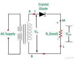
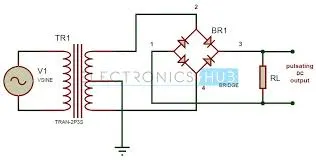
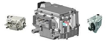
In half wave rectifier the half wave is get at the output if we apply the ac input.
The diode conducts in positive peaks only.
But in case of full wave the diodes number will be incresed to conduct in the negative peaks.
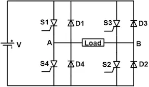
Invertor:
The invertor converts the dc supply into ac supply.
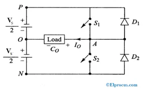
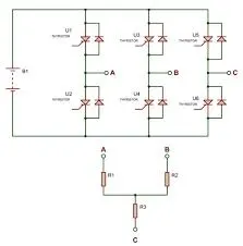
The below diagram represents the inverter ckt.
Based on switches operation the current flows in the load direction changes to produce the ac supply.
The 3 phase inverter consists of three limbs of swiches to 3 phase supply.
power converters in electrical vehicles :
The electrical vehicles consists of differebt power electronics circuit ie,
1.rectifiers
2.inverters
3.choppers
rectifiers :
A rectifier is an electrical device that converts alternating current (AC), which periodically reverses direction, to direct current (DC). ... Others require power sources to drive protective current in the right direction. The most common impressed current voltage sources are rectifiers, which can break down.
The rectifiers used in HEV is same as the in this one .
inverters:
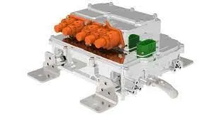
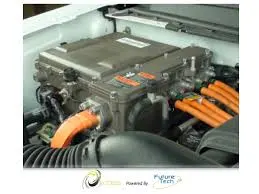
An inverter provides an ac voltage from dc power sources and is useful in powering electronics and electrical equipment rated at the ac mains voltage. In addition they are widely used in the switched mode power supplies inverting stages.
choppers :
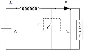
A chopper is a static device that converts fixed DC input voltage to a variable DC output voltage. ... Chopper is fed through a constant DC voltage source and its output is variable DC voltage. The average value of output DC voltage may be less than or higher than the input DC voltage source.
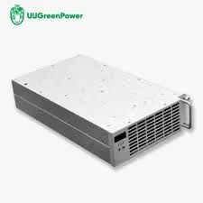
In ev's the charger consists of rectifier and dc to dc converter ,dc to dc converter converts un controlled dc to controlled dc for auxillary lightings and charge the battery voltage at given rating .
types of choppers :
1.buck converter
2.boost converter
3.buck boost converter.
1.buck converter :
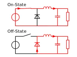
The buck converter is a ubiquitous DC-DC converter that efficiently converts a high voltage to a low voltage efficiently. Efficient power conversion extends battery life, reduces heat, and allows for smaller gadgets to be built. The buck converter can be used in lots of cool applications.
2.boost converter :
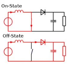
DC-DC converters are also known as choppers. Here we will have a look at the Step Up Chopper or Boost converter which increases the input DC voltage to a specified DC output voltage. A typical Boost converter is shown below.
3.buck boost converter. :
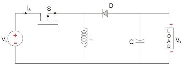
The buck–boost converter is a type of DC-to-DC converter (also knownas a chopper) that has an output voltagemagnitude that is either greater than or less than the input voltage magnitude. It is used to “step up” the dc voltage, similar to a transformer for AC circuits.
It is equivalent to a flyback converter using a single inductor instead of a transformer. Two different topologies are called buck–boost converter.
2.STEADY STATE SPEED FOR 70% DUTY CYCLE FOR AN EV WITH RESPECTIVE PARAMETERS :
battery pack voltage =72v;
Motor and Controller Parameters:
Rated Armature voltage= 72 V ;
Rated armature current= 400 A ;
Ra= 0.5Ω, KΦ= 0.7 Volt second ;
Chopper Switching frequency= 400 Hz ;
The vehicle speed-torque characteristics are given by the below equation
 ....eq1
duty cycle is 70%=0.7 ;
we know that v (avg) terminal voltage =duty cycle*v battery
=0.7*72
=50.4volts
we know,
ω= (V/Kϕ) -(Ra/(Kϕ^2)) *T
ω= (50.4/0.7) -(0.5/(0.7^2)) *T
ω=72-1.02T
T=70.588-0.98ω .....eq 2
from eq 1&2 the T are equal then
70.588-0.98ω =24.7+0.0051ω^2
from solving this we get,
0.0051ω^2+0.9ω-45.888 quadratic equation
solving this equation using
x=(-b±√(b²-4ac))/(2a)
then we got , x=119.96 and -296.43
then speed ω =119.96 Rpm
3.Mathematical model of a DC Motor for the below equation using Simulink:
ω= (V/Kϕ) -(Ra/(Kϕ^2)) *T
Mathematical models:
Any system represented in the form of mathamatical equations is known as a mathematical model.
Mathematical models are critical to understanding and accurately predicting the behavior of complex systems. These models enable critical tasks, such as:
- Forecasting and optimizing system behavior
- Designing control systems
- Characterizing system response
Simulink mathematical model for given equation :
The model typically consists of blocks like:
add-to perform the subtraction block
divide -To perform the division of voltage and kphi parameters.
constant - These blocks for i/p's troque, voltage,Ra,kphi
square - To perforn the kphi^2 operation.
display - display the results of the equation ie, speed.
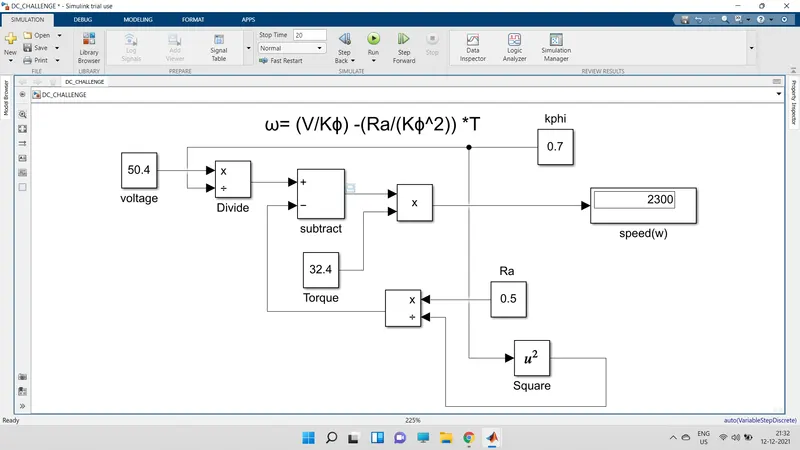
The below fig shows the
voltage = 50.4v,
torque=32.4N-m;
kphi=0.7;
Ra=0.5ohms;
- The output speed is =2300Rpm;
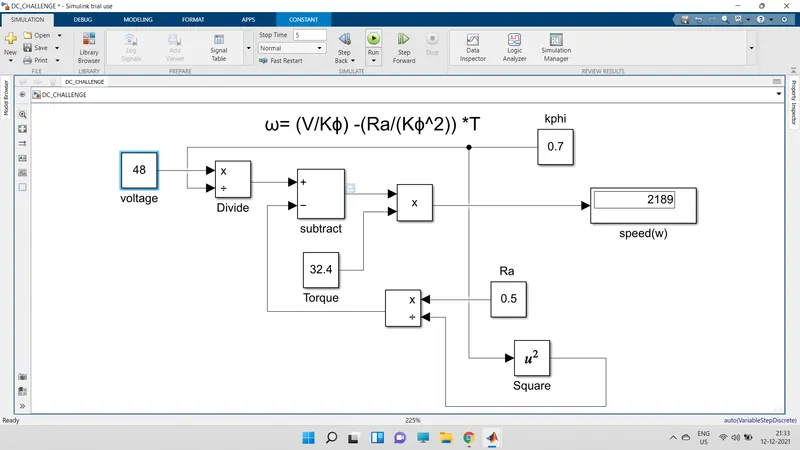
In this case the input voltage is changed to 48 and keeping the remaining parameters constant;
Then the speed =2189Rpm
- we observed that the speed is increses with increse in supply voltage ;for a same motor.
4.BRIEF DETAILS ABOUT INDUCTION MACHINES VS BRUSHLESS MACHINES :
From the authors prospective :
The both machines have their own advantages and disadvantages,we can't say the only machine is good for electrical vehicles.based on our requirements we have to select the machine.
if we consider the conventional vehicle,There is no one best engine type, rather there are different types of engines to suit personal requirements, such as price and performance. This is also true for electric vehicle drives.
Details of BLDC motor :
stator has three phase windings
rotor has 2 or more permanent magnets genrates the dc magnetic flux .
when ever the stator is given with supply from inverter it varies and magnetic flux try to catch the opposite pole it tends the rotor to rotate.
The device stator is controlled by inverter circuit.
LIMITATIONS OF BLDC MACHINE :
The machine requies permanent magnets .
size will be increse increse in magnets.
uiform magnetic field ,B cant be adjusted.
details of induction machine :
The stator has distributed windings similar like bldc motor.
The rotor is squirrel cage rotor , ends are shortcircuited on both side .
when ever 3phase supply is given to the stator it produces an rotating magnetic flux , rotates with synchronous speed
when ever the rotor conductors cuts this flux an emf induces in it .
This emf produces an current in it ,these currents interacts with stator flux and produces an torque on rotor.
The machine has the ability to start at load condition.
No inverter is need
LIMITATIONS OF INDUCTION MACHINE :
These can not operate on dc supply.
If these machines operate at utility power the f is constant so constant speed will obtain.
If connected to utility power the starting torque will below.
If the machine need an inverter to run with variable speed. but limited torque.
From the above data we diffrentiate :
Both DC brushless and induction drives use motors having similar stators. Both drives use 3-phase modulating inverters. The only differences are the rotors and the inverter controls. And with digital controllers, the only control differences are with control code. (DC brushless drives require an absolute position sensor, while induction drives require only a speed sensor; these differences are relatively small.)
One of the main differences is that much less rotor heat is generated with the DC brushless drive.
Rotor cooling is easier and peak point efficiency is generally higher for this drive.
The DC brushless drive can also operate at unity power factor, whereas the best power factor for the induction drive is about 85 percent.
This means that the peak point energy efficiency for a DC brushless drive will typically be a few percentage points higher than for an induction drive.
The magnetic field B is constant due to permanent magnets results in increse in losses hysterisis and eddy current loss and I^2 R losses.
Induction machines have no magnets and B fields are “adjustable,” since B is proportionate to V/f (voltage to frequency). This means that at light loads the inverter can reduce voltage such that magnetic losses are reduced and efficiency is maximized.
comperd to BLDC the B is controlled so performance is improved .and efficiency is more .
cost wisely the BLDC have permanent magnets it cost is too high. and field weekening capability so induction machines are better in this case.
Coming to the controll ,Induction machines are more difficult to control.
The control laws are more complex and difficult to understand. Achieving stability over the entire torque-speed range and over temperature is more difficult with induction than with DC brushless.
His conclusion :
The BLDC motors are likely to dominate in hybrid ,and plug in vehicles ,induction machines in pure electric vehicles based on their high performance.
| PARAMETER | BLDC MACHINE | INDUCTION MACHINE |
| STATOR | 3 PHASE DISTRIBUTIVE | 3PHASE DISTRIBUTIVE |
| ROTOR | PERMANENT MAGNET | SQUIRREL CAGE |
| SENSOR | HALL SENSOR | SPEED SENSOR |
| INVERTER | REQUIRED | REQUIRED,IF NO INVERTER SPEED WILL CONSTANT |
| EFFICICIENCY | HIGH OPERATS AT 1 FREQUENCY | SOME WHAT LESS DUE TO 0.85FREQUENCY |
| SPEED CONTROLL | EASY | DIFFICULT |
| COST | HIGH DUE TO PERMANENT MAGNET | LESS COMPARED TO BLDC |
| MAGNETIC FIELD | CONSTANT DUE TO PERMANENT MAGNET | CHNAGES BASED ON V/F |