Week - 4
Qestion1 :
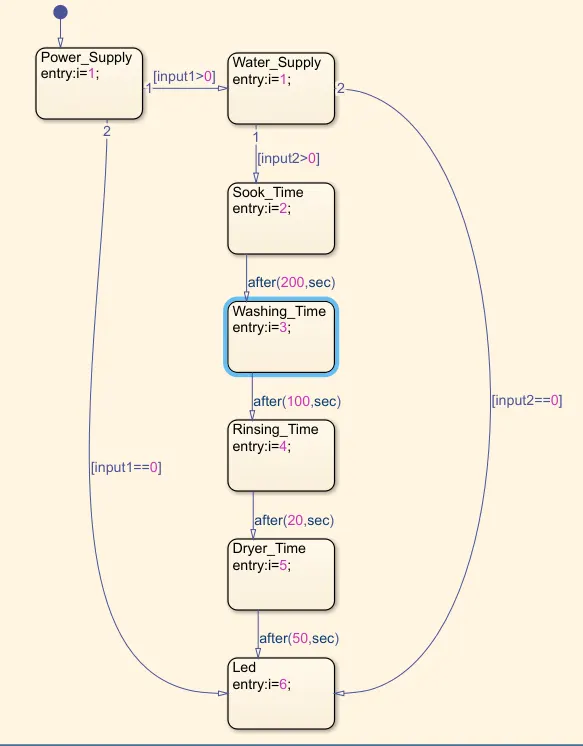
Aim of the Experiment: Implement control logic of a “washing machine” using Stateflow as per given sequence:
- If the power supply is available, the system gets activated
- If the Water supply is not available, stop the process & indicate through LED
- Soaking time should be 200s followed by Washing time of 100s.
- Then rinsing happens for next 20s & dryer runs for 50s
Theory of the Experiment: The Working Principle of Washing Machine is "Centrifugation". Centrifugation is a separation process that uses the action of centrifugal force to promote accelerated settling of particles in a solid-liquid mixture. The washing machine contains some important parts like, drum,value,pump,motor,pump,heating.The process involved in washing machine is Soaking,Washing,Rinsing,Dryer.For the better understanding....
Soaking: In this process clothes dip in detergent water to remove dirt from them.This function can be selected form control pannel.
Washing: During this process, a large plastic which was specially made is attached to the walls of the drum, which support the machine in washing process.After the washing completed, the washed water is pumped out of the drum.
Rinsing:In this process dirty and soap water is drained,then the washing machine drum is refilled with clean water for washing the clothes for second time. After this happend a sub-process will start, i.e, namely Spin, in this process the drum started to revolve at faster phase so that the remained water and absorbed water by clothes will be drained out, by the centriful force acting on the clothes.
Dryer: During this process, pushing the warm dry air thrugh your wet washing to extract moisture, then cooling the humid air in a heat exchanger to condense the moisture, this cycle is contious in this way the entire washing cycle is perfromed in all the washing machines.
Modeling of the Experiment: This modelling is done with state flow as it is the requirement of the question.The below pic explan the logic of the washing machine in state flow.
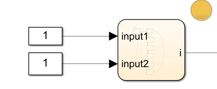
The below pic explane the complete logic diagram with INPUT BLOCK'S
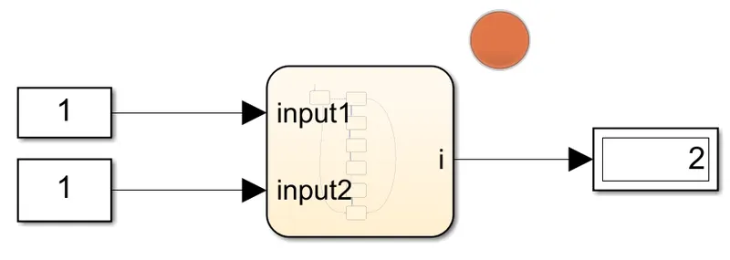
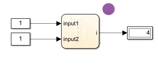
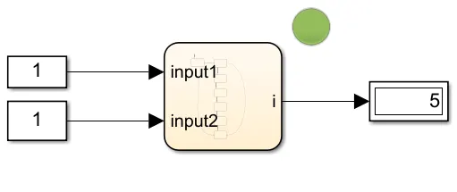
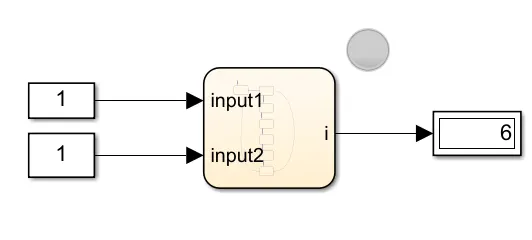
Output of the Experiment: The below output is taken at different run time levels.
@10sec : At this point the dispaly is showing 2 for that we asinged the colour red, that is seen in LED.
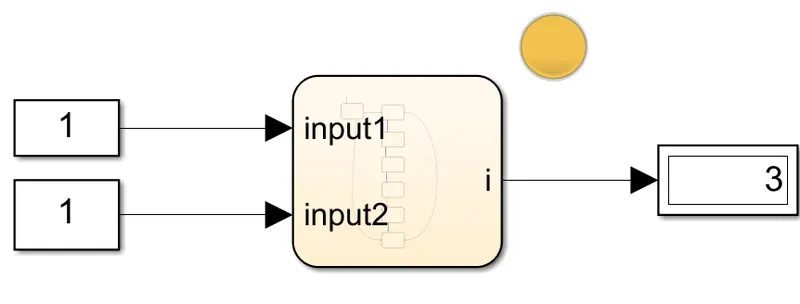
@250 sec : At this point the dispaly is showing 3 for that we asinged the colour yellow, that is seen in LED.
@320 sec: At this point the dispaly is showing 4 for that we asinged the colour violet, that is seen in LED.
@350 sec : At this point the dispaly is showing 5 for that we asinged the colour green, that is seen in LED.
@400 sec : At this point the dispaly is showing 6 for that we asinged the colour gray, that is seen in LED.
Result of the Experiment:
Hence the required result was achived, aim of the experiment was obtained.
Question-2 :
Aim of the Experiment:
To Make a Simulink chart for the “Gear shift” logic as per below conditions:
Speed Range(kmph) Gear
0 to 15 1
16 to 25 2
26 to 40 3
41 to 60 4
Above 61 5
Give speed input while the simulation is running & display the gear number.
Theory of the Experiment: A gear shift mechanism is very common in manual transmission cars, it also includes a shaft axially movable for selecting shift planes and rotatable for engaging the gears defining the shift planes. The shaft is held in a reference shift plane by two helical springs. The below digram shows the logic of the gear shif using state flow.
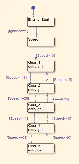
Modelling of the Experiment: The entire modelling is shown in the SC, with the input blocks,
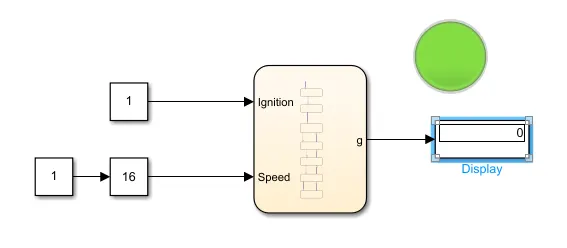
Output of the Modelling:
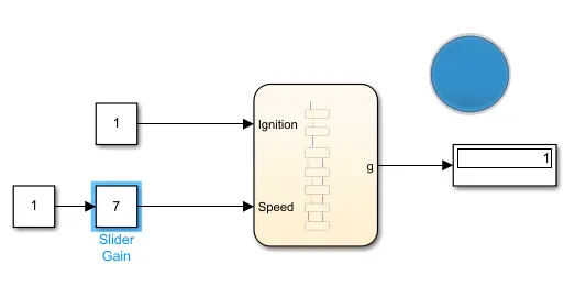
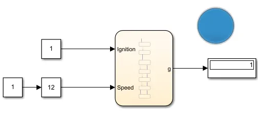
Speed range between 0 to 15 kmph: In this stage we checked with 2 different speeds levels that is 7 & 12 which are between required speed level, for that we asinged a colour bule for this.
@7 kmph
@12 kmph
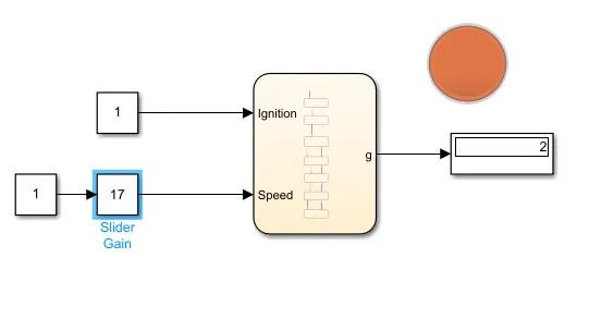
Speed range between 16 to 25 kmph: In this stage we checked with 2 different speeds levels that is 17 & 24 which are between required speed level, for that we asinged a colour red for this.
@17 kmph
@24 kmph
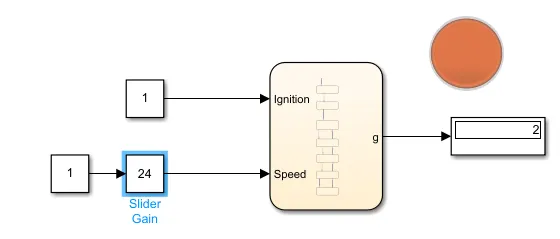
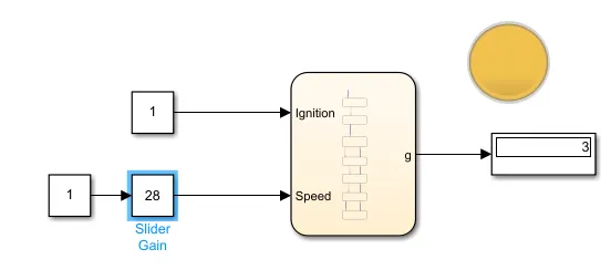
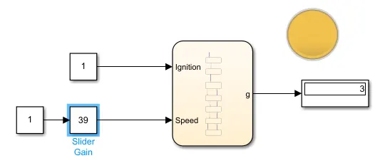
Speed range between 26 to 40 kmph: In this stage we checked with 2 different speeds levels that is 28 & 39 which are between required speed level, for that we asinged a colour yellow for this.
@28 kmph
@39 kmph
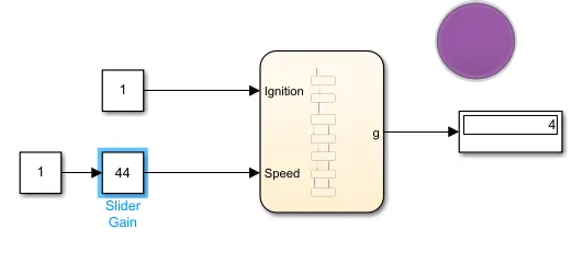
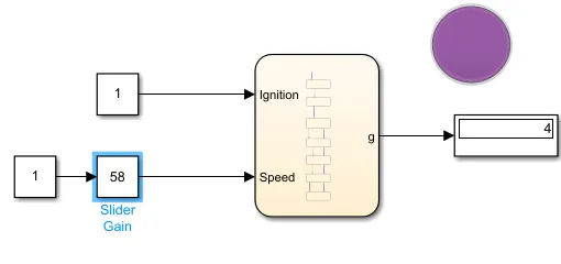
Speed range between 41 to 60 kmph: In this stage we checked with 2 different speeds levels that is 44 & 58 which are between required speed level, for that we asinged a colour violet for this.
@44 kmph
@58 kmph
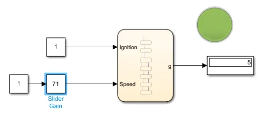
Speed range above 61 kmph: In this stage we checked the speeds levels 61 kmph i.e we have take 71kmph which is required speed level, for that we asinged a colour green for this.
Result of the Experiment:
Hence the required result was achived, aim of the experiment was obtained.