Week -2
Question 1 :
Make a Simulink model of Doorbell using solenoid block :
Objective of the Question: To make the Doorbell using soleniod using simulink arrangement,with the requirments of
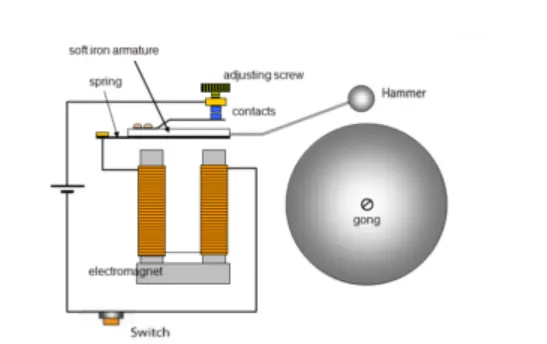
- The switch should be closed when the electromagnet receives electrical power from the battery and pulls the metal arm to hit the bell producing sound.
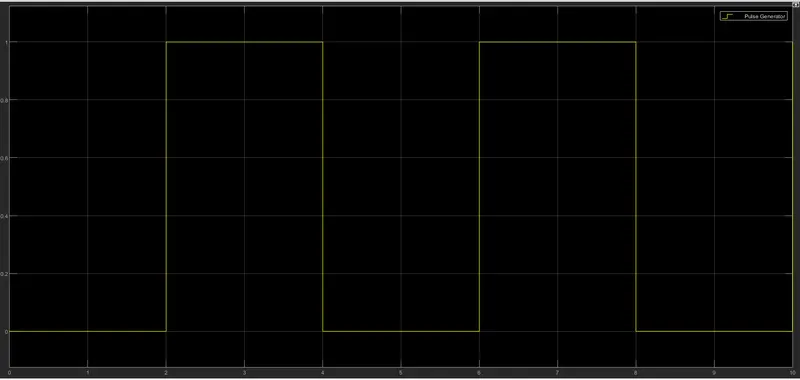
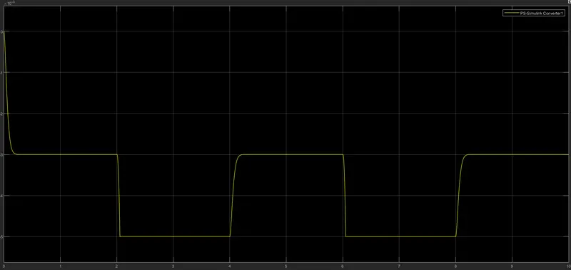
- Creation of a situation where the switch must be closed for 2 seconds and then release. Observe the physical movement of the plunger.
Discription of the Simulink modeling:
DoorBell: we all are very familier with the door bell which is common in all the house holds now a days. To under the working of the DoorBell in simple terminology, an electrical switch is present outside the house when we press that switch the electrical circuit close and the power will be taken from either from battery or from electrical supply. For the better understanding the below digramatic representaion will help us alot..
Solenoid: It is a long piece of wire which is wound in the shape of a coil. When the electric current passes through the coil it creates a relatively uniform magnetic field inside the coil.The below diagramatic representaion provies us better understanding of the soleniod.
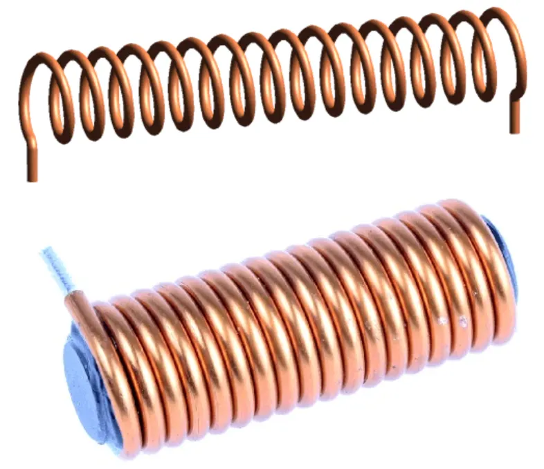
The solenoid simply works on the principle of “Electromagnetism”. When the current flow through the coil magnetic field is generated in it, if you place a metal core inside the coil the magnetic lines of flux is concentrated on the core which increases the induction of the coil as compared to the air core. The magnetic strength of the solenoid can be increased by increasing the density of the turns or by increasing the current flow in the coil.Like all other magnets the activated solenoid has both Positive and Negative poles, through which an object can be attracted or repelled.
Simulink Model for DoorBell with Solenoid :
Blocks used for the construction of the below simulink model,
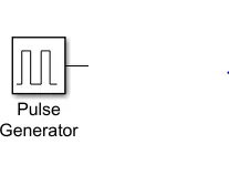
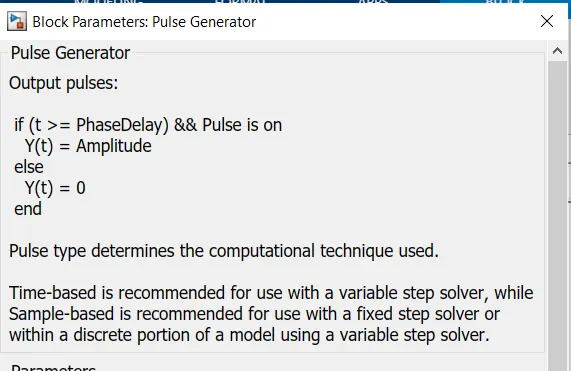
Pulse Genertor: Used to generate the square wave pulse at a required time intervals. In this we can change the parameters like Amplitude,Pulse width,period & phase delay. So accordingly we can determine the shape of the waveform.
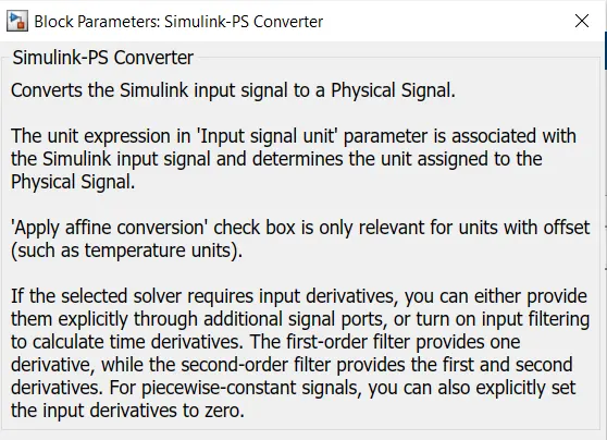
Simulink-PS Converter: This block does the function to convert the unitless Simulink input signal to a Physical signal.
Scope: Used to observer graphical representation at input & output.
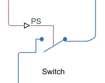
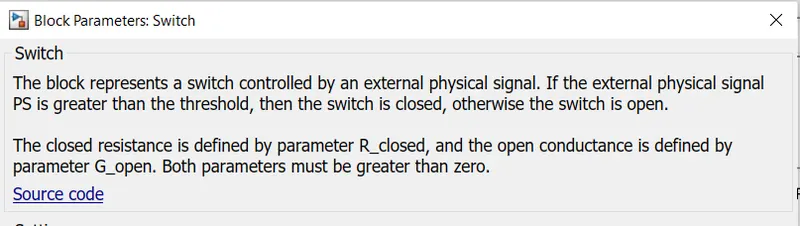
Switch: This switch is controlled by an external physical signal.
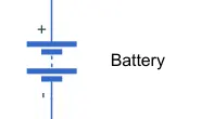
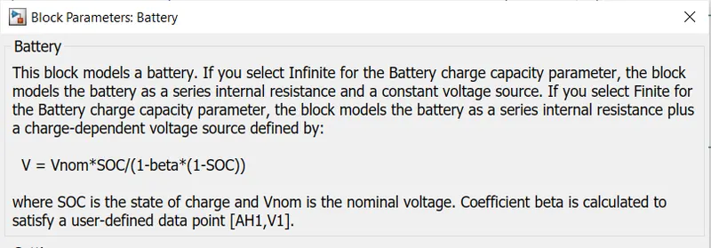
Battery: The battery block is used a power supply for the entire circuit.
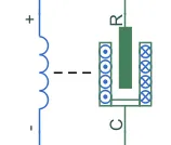
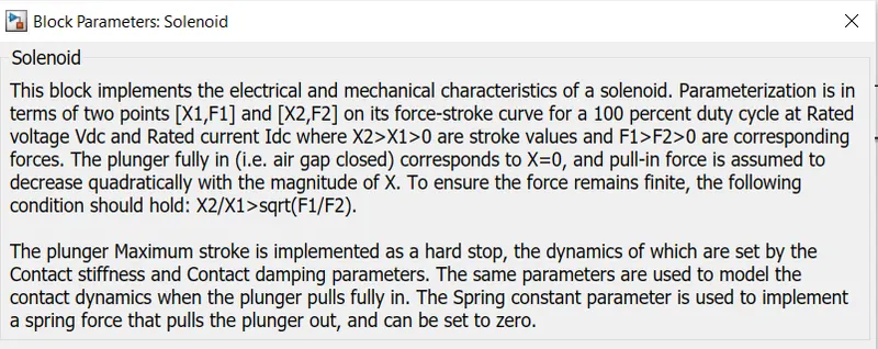
Solenoid: This block is used to generate the required electrical characteristics and force of the solenoid.
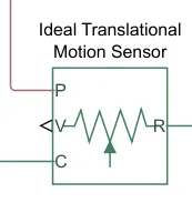
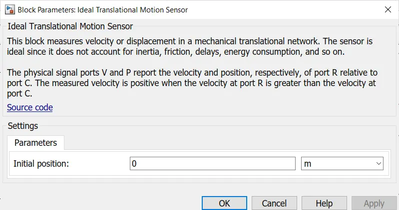
Ideal Translational Motion Sensor: With help of this block we can specify the initia position as a block parameter. The Sensor is ideal, so it won't consider the account of inertia, friction,delay,energy consumption and...
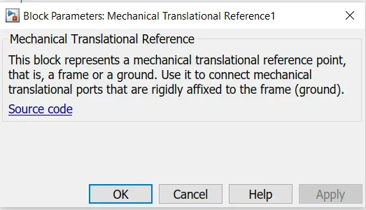
Mechanical Translational Reference: This block represent the reference point, for all the mechanical translation blocks

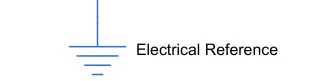
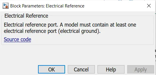
Electrical Reference: Its function is also same as that of mechanical translational Reference but only diffrence is it provide the ground for the electrical blocks.
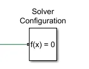
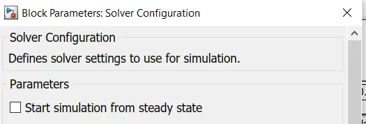
Solver Configuration: This block is used to specifies the solver parameters that our model needs before we can begin the simulation.
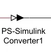
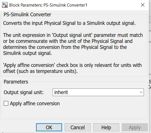
PS Simulink Converter: This bock is used to convert physical signal into simulink output signal.
Modeling of DoorBell using Simulink:
Construction steps for the above simulink block:
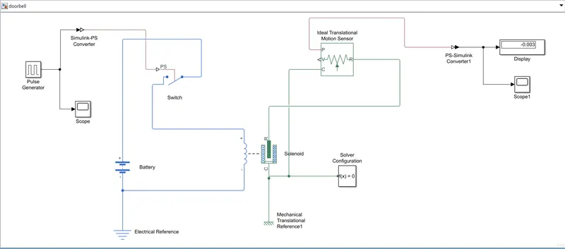
- From the Pulse Generator once the signal is fed to simulink PS Converter, the input signal is converted into physical form and then send to electrical circuit.
- We know that the electriacl circuit is consists of a switch,battery, & a soleniod. one sie of the soleniod is coonected to the battery and other end is connected to switch.
- And for proper grounding, electrical reference is provided to the electrical circuit.
- And mechanical reference is also connect for the same perpose as like of electrical reference.
- The sensor terminal P makes the connection with PS-Simulink Converter to provide the output in the signal form
- From theoutput of PS-Simulink Converter the connection is given to scope to display the signal
- Finally a Solver configuration is connected to an electrical circuit to deal with all the parameters before the beginning of the Simulink.If not Matlab show the error.
Graphical Representaion of Modeling:
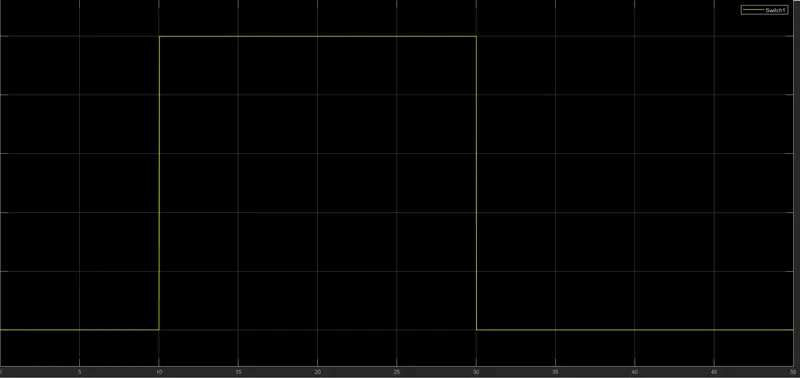
Input of the Modeling:
Output of the Modeling:
Question-2
Objective of the Question: By using a thermistor to sense the temperature of a heater & turn on or turn off the fan as per the below conditions:
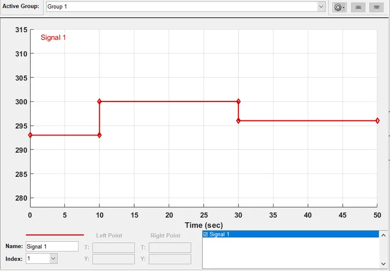
- Temperature source: 20 °C from 0 to 10 seconds, 27 °C from 10 to 30 seconds, 23 °C from 30 to 50 seconds.
- Fan conditions: ON if the temperature above 25 °C, OFF otherwise.
Intorduction to the model block's:
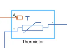
Thermistor: A thermistor is made of oxides of metals such as Nickel, Manganese, Cobalt, Copper, Uranium etc. It is available in a variety of shapes and sizes. Commonly used for configurations are Disk type, Bead type and Rod type.
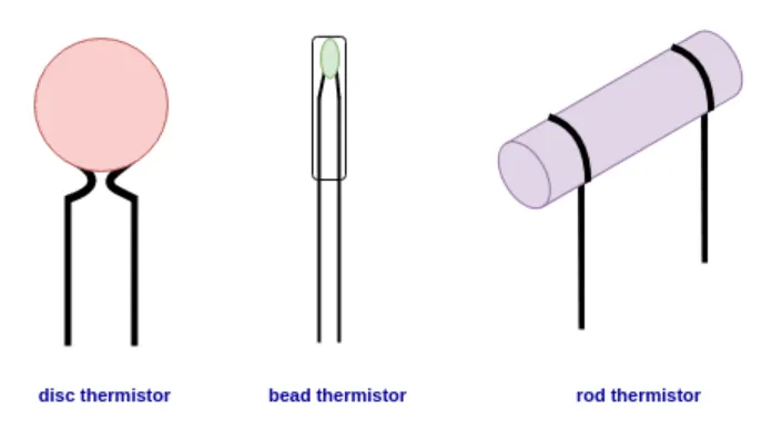
The measurement element is typically encapsulated in a glass probe. It is commonly used for measuring the temperature of liquids.The thermistor works on the simple principle of change in resistance due to a change in temperature. When the ambient temperature changes the thermistor starts self-heating its elements. its resistance value is changed with respect to this change in temperature. This change depends on the type of thermistor used. The resistance temperature characteristics of different types of thermistors are given in the following section.
NTC stands for Negative Temperature coefficient. The resistance of an NTC will decrease with increasing temperature in a non-linear manner.
PTC stands for Positive Temperature Coefficient. The resistance of a PTC will increase with increasing temperature in a non-linear manner.
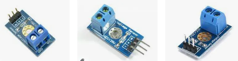
Voltage Sensor: A voltage sensor is a sensor used to calculate and monitor the amount of voltage in an object. Voltage sensors can determine the AC voltage or DC voltage level. The input of this sensor is the voltage, whereas the output is the switches, analog voltage signal.
Required Blocks for Modeling:
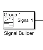
Signal Builder: It is used to create the signal input as of our requirement. So the below showed input signal is the ploted as the question asked. This signal can also be called as input signal.
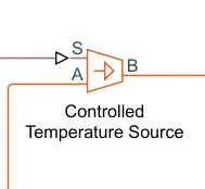
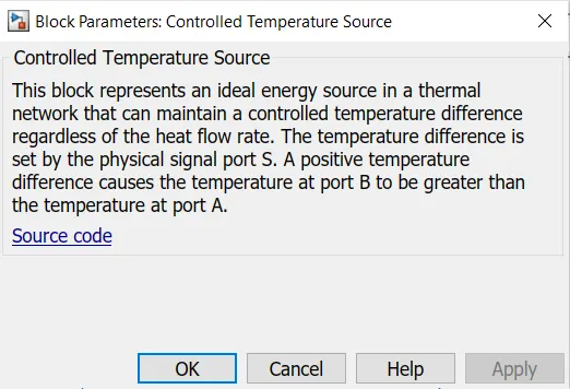
Controlled Temperature Source: The below matlab Screen short will explain the needfull about this block.
Voltage Sensor: This block is used to sence the different voltages which are genareted different resistance because of the different temperature.
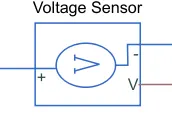
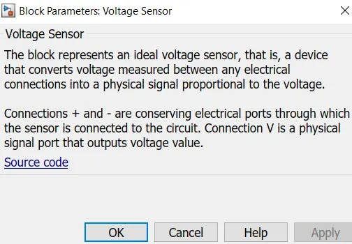
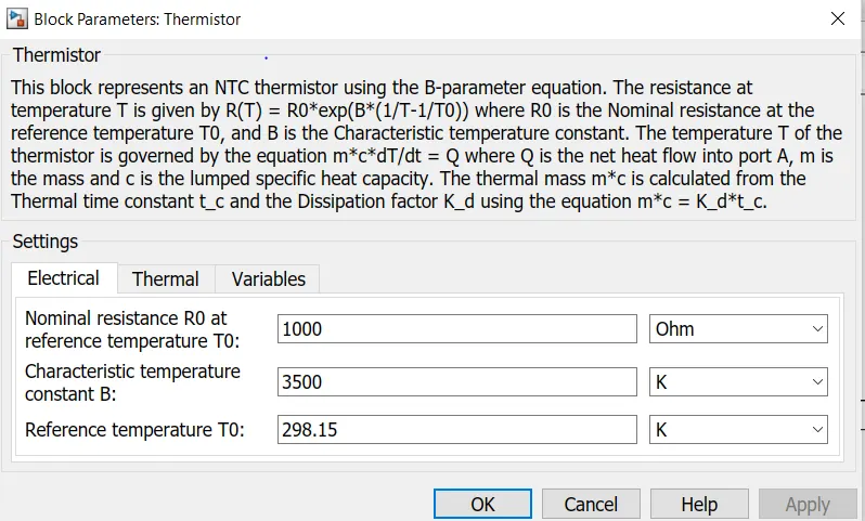
Thermistor: It helps in measurement element is typically encapsulated in a glass probe. It is commonly used for measuring the temperature of liquids.The thermistor works on the simple principle of change in resistance due to a change in temperature. When the ambient temperature changes the thermistor starts self-heating its elements.
Construction of the Simulink:
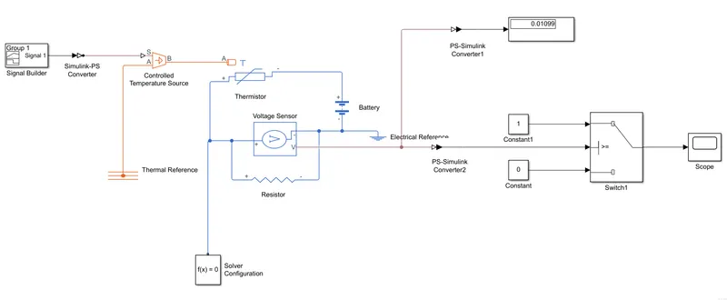
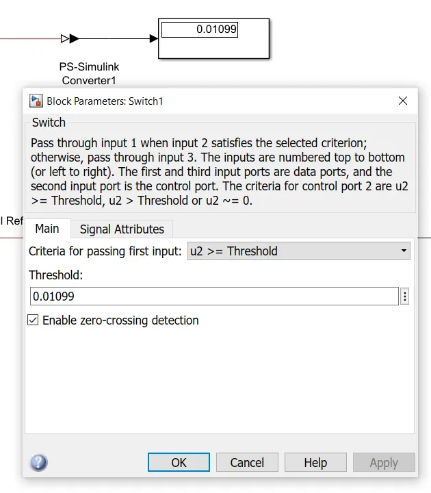
Process of Performing: After performing the simulink construction. Press Ctrl+T then the simulink will run, then in display we will get the value. After getting that, Take that as threshold value and set it in the switch which is present in simulink. This is the important step that we need to do to get the required output. The same is explained in below images
Output: After doing Ctrl+T the below graphical represention is shown in the scope, It is clear that the output is achieved as per the requirements.