Week-7 Challenge: DC Motor Control
Question 1.
Simulation model:
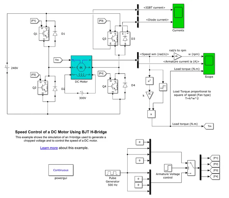
A) This is the simulation of an H-bridge which is used to generate a chopped voltage and also to control the DC motor speed.
When BJT is used for power switching applications it operates as IGBT. When it is conducting which means it is operating in saturation region a forward voltage is developed b/w emitter and collector so, IGBT block can be used to model BJT.
The H-bridge consists of four BJT simulated by IGBT models /Diode pairs. Two transistors are switched simultaneously: Q1 and Q4 or Q2 and Q3. When Q2 and Q3 are fired, a negative voltage is applied to the motor, and diodes D1-D4 operate as free-wheeling diodes when Q2 and Q3 are switched off. When Q1 and Q4 are fired, a positive voltage is applied to the motor, and diodes D2-D3 operate as free-wheeling diodes when Q1 and Q4 are switched off.
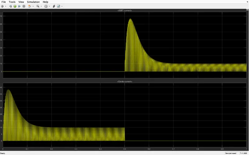
B) IGBT Current, Diode Current vs Time
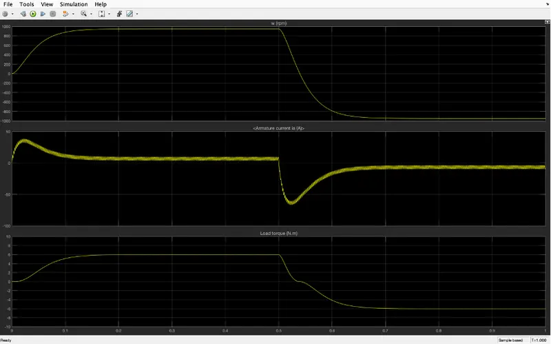
Armature current, Load Torque vs Time
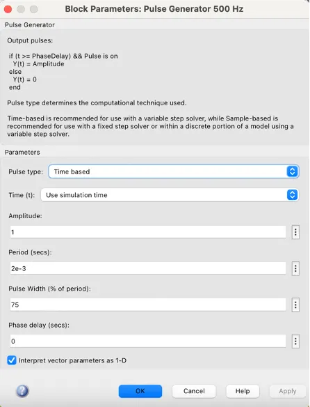
You can see pulse width is 75% which means the program is on for 75% of the time and off for 25% of the time.
We can see that for Q3 and Q4 the input is given after 0.5 seconds so the IGBT signal starts after 0.5 seconds.
Current passes through the diode only during the first half of the cycle.
Pulse width is changed to 50%
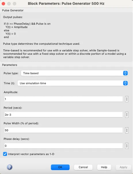
Armature current vs Time
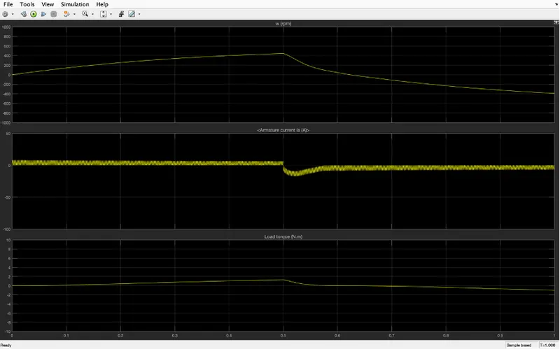
We can observe reducing duty cycle from 75% to 50% armature current changing direction has reduced.
C)
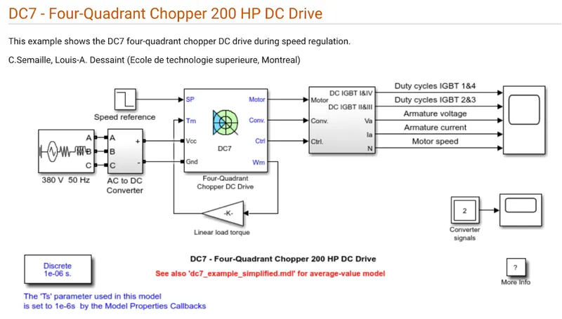
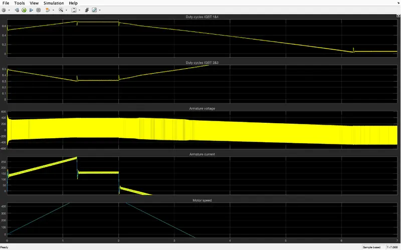
Comparison:
For DC7 - Four-Quadrant Chopper 200 HP DC Drive current for each sector is required and also consists of four-quadrant forward motoring, reverse motoring, forward regenerative braking, and reverse regenerative braking.
H-bridge consists of only forward motoring and reverses motoring.
In DC7 - Four-Quadrant Chopper 200 HP DC Drive to change the direction of rotation of motor the current signal is interrupted with one another.
In BJT to change the direction of rotation of motor polarity of the current is changed.
In DC7 - Four-Quadrant Chopper 200 HP DC Drive PID controller to control and in H-bridge model this is not used.
Question 2.
Circuit diagram for 2-quadrant chopper
Now we have to make a simulation according to the circuit diagram for a 2-quadrant chopper
Simulation:
We have used:
- Powerful
- Pulse Generator
- DC Voltage Source
- NOT Operator
- Mosfet
- Diode
- Current Measurement
- Series RLC Branch with only inductor
- Voltage Measurement
- Scope
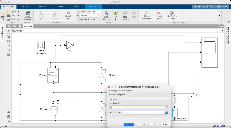
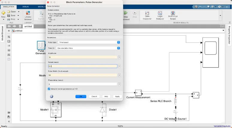
Changing Parameters 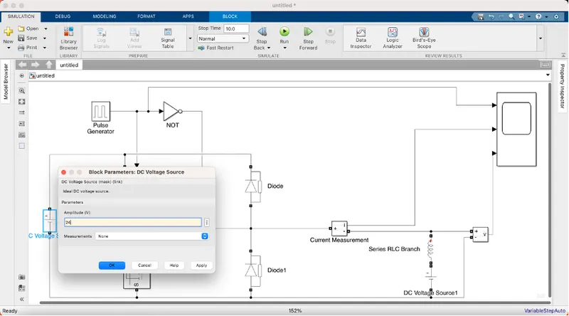
Results from scope:
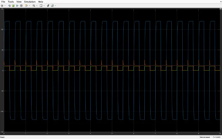
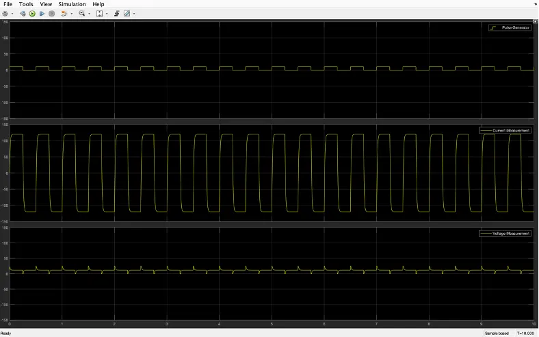
From the result, we can clearly see that voltage is never going to 0 and always lying on the positive side of the axis
Current is increasing and decreasing and also lying in both positive and negative axes.
Question 3.
BLDC- Brushless DC motor
DC motor which does not have brushes and controller provides current pulses to the motor winding which controls the torque and speed of the motor is BLDC.
In brushless motors, the problem of connecting current to the armature is overcome by permanent magnets rotating around a fixed armature. Over a vast speed range, these types of motors are very efficient in producing large amounts of torque.
Working principle:
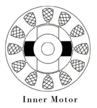
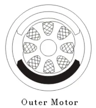
There are only two basic parts in the BLDC motor they are stator and rotor. The stator is the resting part and contains windings the rotor is a rotating part and contains magnets. In BLDC permanent magnets are attached to the rotor and move the electromagnets to the stator.
To activate electromagnets for the shaft turns high power transistors are used. Using a solid-state circuit the controller performs power distribution.
Types of BLDC
1. Inner rotor design
2. Outer rotor design
Advantages of BLDC:
- More efficient because the velocity of BLDC is determined by the frequency at which the current is applied and does not depend on voltage.
- Mechanical energy losses because of friction are less due to the absence of brushes.
- Can operate at high speed under any condition.
- Less noise and no sparking under any condition
- For much more precise control, more electromagnets can be used
Disadvantages of BLDC:
- Cost is higher compared to brushed dc motor
- Only limited power could be supplied to the motor because the high amount of heat weakens the magnets and insulation may get damaged.