Week -2
- Make a Simulink model of Doorbell using a solenoid block with the following details:
In the above arrangement, when the switch is closed the electromagnet receives electrical power from the battery and pulls the metal arm to hit the bell producing sound.
Create a situation where the switch is closed for 2 seconds and then released. Observe the physical movement of the plunger.
Assume remaining parameters.
Solution:
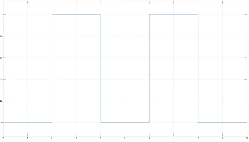
To generate the required input pulse for which the switch will be closed for 2 seconds and released, we need to take the following parameters.
- Amplitude: 1
- Period: 4s
- Pulse width: 50% of the period
- Phase delay: 2s
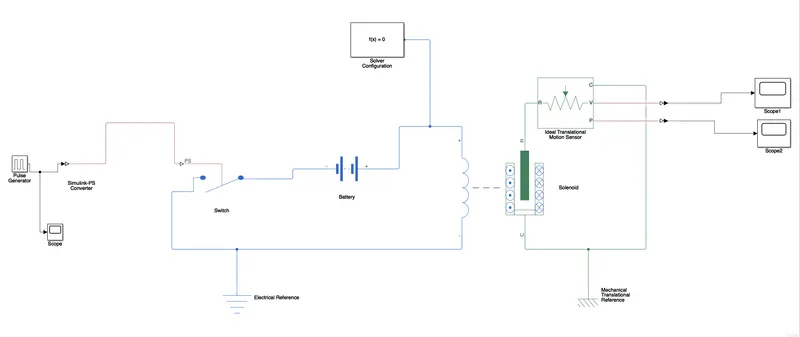
The solenoid is connected to a battery and it is connected to a switch to control it. A pulse wave block was attached to switch with the help of a Simulink-ps converter to get desired input pulse.
Screenshot of the simulated model:
input pulse wave:
The mechanical part of the solenoid is connected to an ideal translational motion sensor and the velocity and position can be observed through scope blocks using a ps-Simulink converter.
The angular velocity scope:
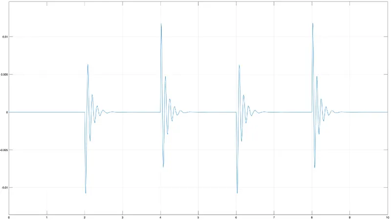
The position scope of solenoid:
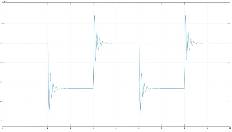
As we can observe from the graphs the vibration when the switch is on for 2 seconds the solenoid gets charged and the plunger hits the bell. It again gains its neutral state after some time through damping when the switch is turned off for 2 seconds.
The same can be observed from the angular velocity and position of the plunger with respect to time.
2. Use a thermistor to sense the temperature of a heater & turn on or turn off the fan as per the below conditions:
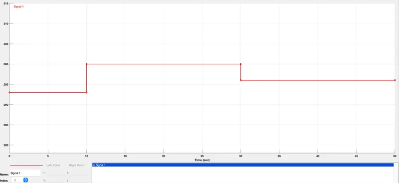
Temperature source: 20 °C from 0 to 10 seconds, 27 °C from 10 to 30 seconds, 23 °C from 30 to 50 seconds
Fan conditions: ON if the temperature is above 25 °C, OFF otherwise.
Screenshot of the simulated model:
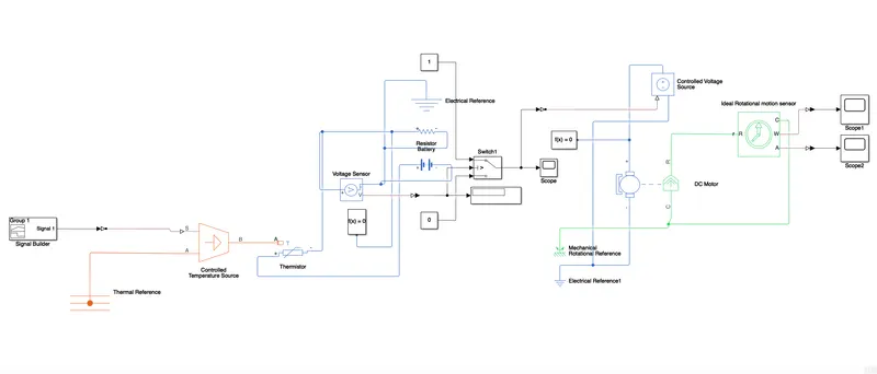
To set the temperature as 20 °C from 0 to 10 seconds, 27 °C from 10 to 30 seconds, 23 °C from 30 to 50 seconds we used signal builder. We connected signal builder to temperature source for the desired inputs. As mentioned in the question, we used thermistor to sense the temperature.
Input temperature pulse wave:
We need to know the voltage so that we could turn ON or OFF the fan. So, we used voltage sensor and attached it to switch which is connected to control voltage source through which voltage is controlled in DC motor which in other words is fan.
As per the given condition the fan should be turned ON when the temperature exceeds 25 °C otherwise OFF.
Voltage graph: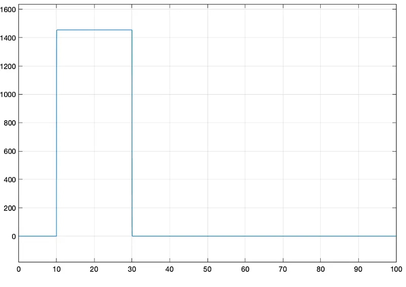
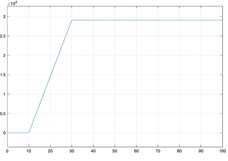
From the graph we can observe that the voltage is present only from 10s to 30s as the input temperature exceeds 25 °C only between that interval.