Week-7 Challenge: DC Motor Control
Week 7 -Challenge
Part 1 Speed control of a DC motor using BJT H-bridge-
The Bipolar Junction Transistor (BJT) when used for power switching applications, operates as an IGBT. When it is conducting (BJT operating in the saturated region), a forward voltage Vf is developed between collector and emitter (in the range of 1 V). Therefore, the IGBT block can be used to model the BJT device.
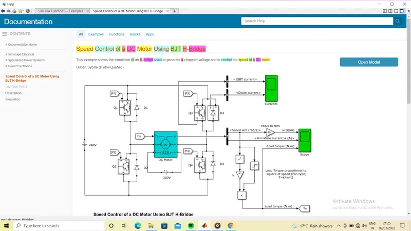
The H-bridge consists of four BJT/Diode pairs (BJT simulated by IGBT models). Two transistors are switched simultaneously: Q1 and Q4 or Q2 and Q3. When Q1 and Q4 are fired, a positive voltage is applied to the motor and diodes D2-D3 operate as free-wheeling diodes when Q1 and Q4 are switched off. When Q2 and Q3 are fired, a negative voltage is applied to the motor and diodes D1-D4 operate as free-wheeling diodes when Q2 and Q3 are switched off.
(A) Armature current shoot-up -
Here is model 'speed control of a DC motor using BJT H-bridge. Open this model in simulink and run it keeping all default parameter-
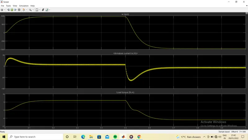
After running the model we find that there is shoot up in armature current when direction of speed changes. We can reduce this shoot up by changing duty cycle of pulse generator.
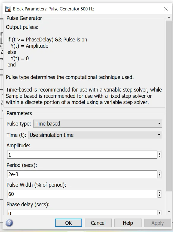
As in model by default value of pulse width is 75%. Lets change it to 60% and then observe the result.
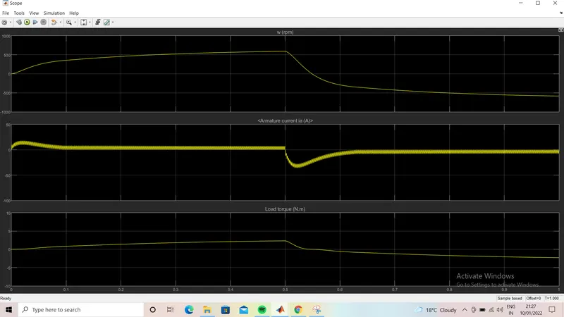
After changing pulse width to 60%, the scope result is following. Here we clearly observe that as pulse width decreases the current shoot up also decreases. But simultaneously the value of speed also decreases as we decrease the pulse width.
(B) Comparison of 'The Four-Quadrant Chopper DC Drive (DC7) block’ with H-bridge model-
The 200 HP DC motor is separately excited with a constant 150 V DC field voltage source. The armature voltage is provided by an IGBT converter controlled by two PI regulators. The converter is fed by a 515 V DC bus obtained by rectification of a 380 V AC 50 Hz voltage source. In order to limit the DC bus voltage during dynamic braking mode, a braking chopper has been added between the diode rectifier and the DC7 block.
There is alot of differences between these two model. Lets compare it-
- In H-bridge model DC source is used but in DC7-model three phase AC supply is used then it is converterd into DC using rectifier.
- In H-bridge model, there is seperate block of DC motor and switches used for controlling motor, but in DC7 model motor and its controller is represented by a single block.
- The behaviour of load torque is linear in DC7-model and in H-bridge model it is fan load type i.e. quadratic in nature.
- In H-bridge pulse generator is used for controlling switching of powerelectronic devices but there is no such arrangement in DC7 model.
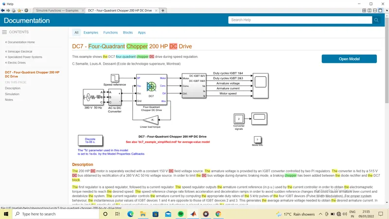
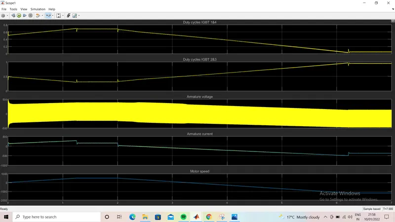
- Regeneration is possible in DC7 model but not in BJT H-bridge model.
- It is more widely used in automobile sector as compare to BJT model.
Part 2 Two quadrant chopper model in simulink-
In power electronics chopper circuit , unidirectional power semiconductors are used. If these semiconductor devices are arranged appropriately, a chopper can work in any of the four quadrants. we can classify chopper circuits according to their working in any of these four quadrants as type A, type B, type C, type D and type E. Let us now take a look of these classifications and the characteristics of various classifications.
Type C chopper is obtained by connecting type –A and type –B choppers in parallel. We will always get a positive output voltage V0 as the freewheeling diode FD is present across the load. When the chopper is on the freewheeling diode starts conducting and the output voltage v0 will be equal to Vs . The direction of the load current i0 will be reversed. The current i0 will be flowing towards the source and it will be positive regardless the chopper is on or the FD conducts. The load current will be negative if the chopper is or the diode D2 conducts. We can say the chopper and FD operate together as type-A chopper in first quadrant. In the second quadrant, the chopper and D2 will operate together as type –B chopper.
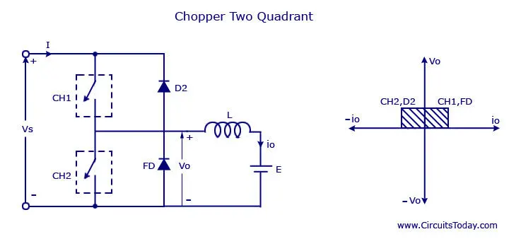
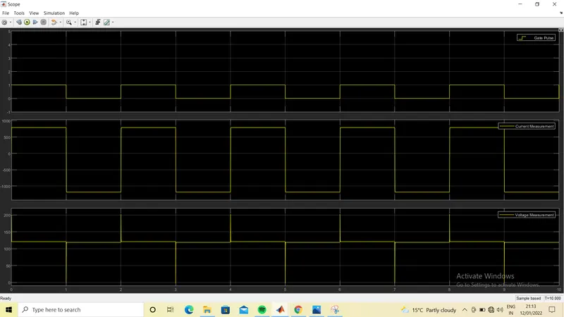
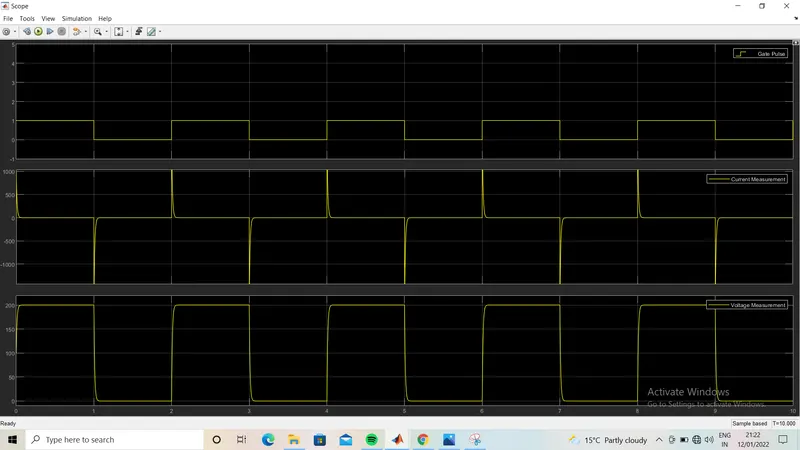
Here I have designed two chopper in simulink that operate in 1st and 2nd quadrant which the output voltage will always be positive but direction of current will change. When the upper MOSFET in model is ON the current will in positive direction and when another MOSFET will ON the current direction will be negative.
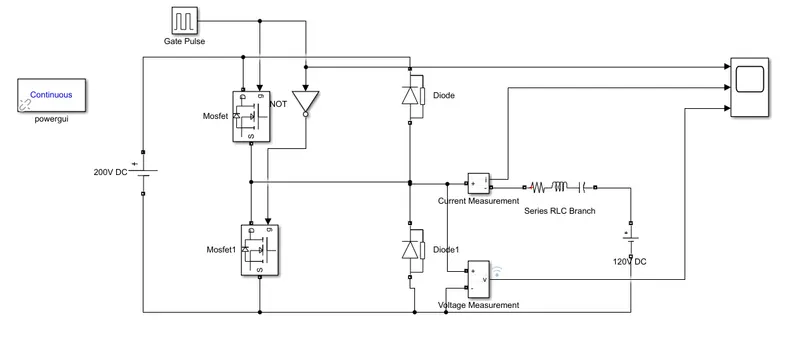
In above model we have used pulse generator block for turning ON and OFF the MOSFET. RLC branch is used as load along with 120 V DC. Lets see scope result for different value of R,L and C-
When R= 0.001 L= 1e-6 and C= 0 :
When R= 0.001, L = 0, and C= 1e-6 :
When R= 0.001, L= 0, C= 0 :
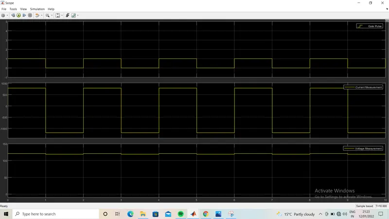
In all result we can see that the current direction changes from positive to negative and vice-versa. Voltage remains positive. But shape of wavefrom is different depending on values of R, L and C.
Part 3 Operation of BLDC motor-
A brushless DC motor (known as BLDC) is a permanent magnet synchronous electric motor which is driven by direct current. BLDC motors are also referred as trapezoidal permanent magnet motors. Unlike conventional brushed type DC motor, wherein the brushes make the mechanical contact with commutator on the rotor so as to form an electric path between a DC electric source and rotor armature windings, BLDC motor employs electrical commutation with permanent magnet rotor and a stator with a sequence of coils. Hall sensors are used to sense the position of the rotor and are positioned around the stator. The rotor position feedback from the sensor helps to determine when to switch the armature current.
BLDC motor works on the principle similar to that of a conventional DC motor. In BLDC motor, the current carrying conductor is stationary while the permanent magnet moves, when the stator coils are electrically switched by source, it starts producing the uniform field in the air gap. As supply is DC but switching makes to generate an AC voltage waveform with trapezoidal shape. Due to the force of interaction between electromagnet stator and permanent magnet rotor, the rotor continues to rotate.

Observe that motor produces torque because of the development of attraction forces and repulsion forces. Hall sensors give shaft position feedback to the electronic controller unit. Accordingly we know which stator coil should be energized and when to do.